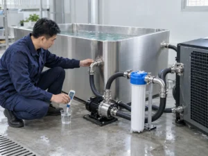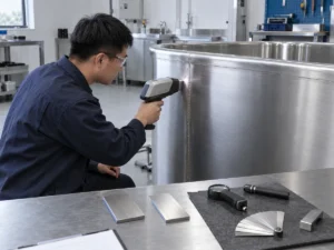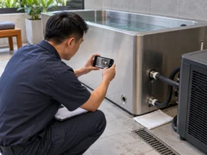
El volumen de agua de la inmersión fría es un dato de ingeniería determinante, no solo una capacidad de catálogo. Para una tina horizontal, el número útil es el volumen de agua vinculado a un nivel de funcionamiento definido y a una configuración exacta; para algunos cálculos, el límite también debe incluir el agua contenida en tuberías externas, filtros, intercambiadores de calor o componentes de amortiguación.
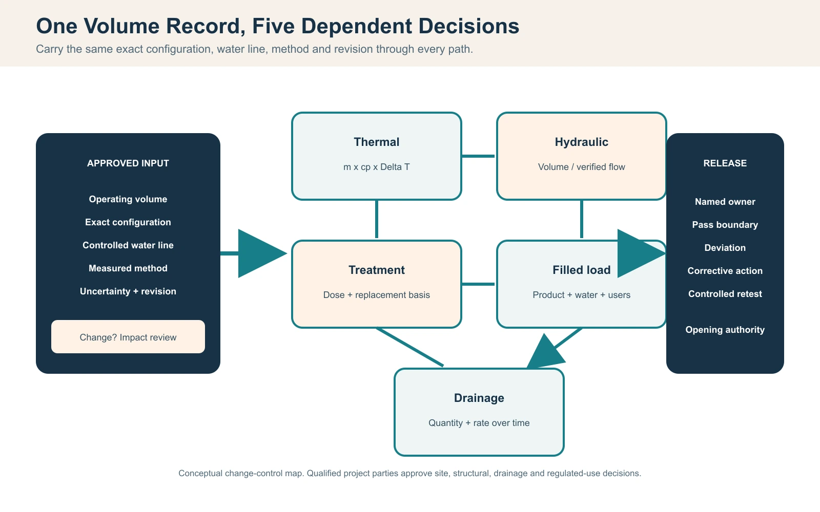
Respuesta directa: Más agua aumenta la energía del lado del agua que debe eliminarse para el mismo cambio de temperatura, cambia la base aritmética de recambio, afecta las cantidades de tratamiento y reposición, aumenta la masa operativa llena y puede incrementar la cantidad planificada de vaciado. No infiera ese volumen a partir de las dimensiones exteriores o de un modelo relacionado. Verifique el volumen operativo de la tina en una referencia repetible de la línea de agua, defina si se incluye el circuito conectado, registre el método de medición y la incertidumbre, y traslade la misma base aprobada a los registros térmicos, hidráulicos, estructurales, de tratamiento y drenaje. Si el nivel de agua aprobado, la geometría interna o el circuito conectado cambian, revise cada decisión dependiente antes de confiar en el resultado anterior.
Entrada principal: Volumen operativo verificado de la tina en una cota de referencia controlada de la línea de agua, con el límite del circuito conectado declarado.
Regla de cálculo: Use las unidades y condiciones declaradas para los cálculos de energía del agua, enfriamiento útil, caudal, masa y descarga.
Límite de liberación: Vuelva a verificar las decisiones dependientes cuando cambie la base de volumen aprobada o la configuración.
Defina qué volumen de agua de la bañera de inmersión en frío quiere decir
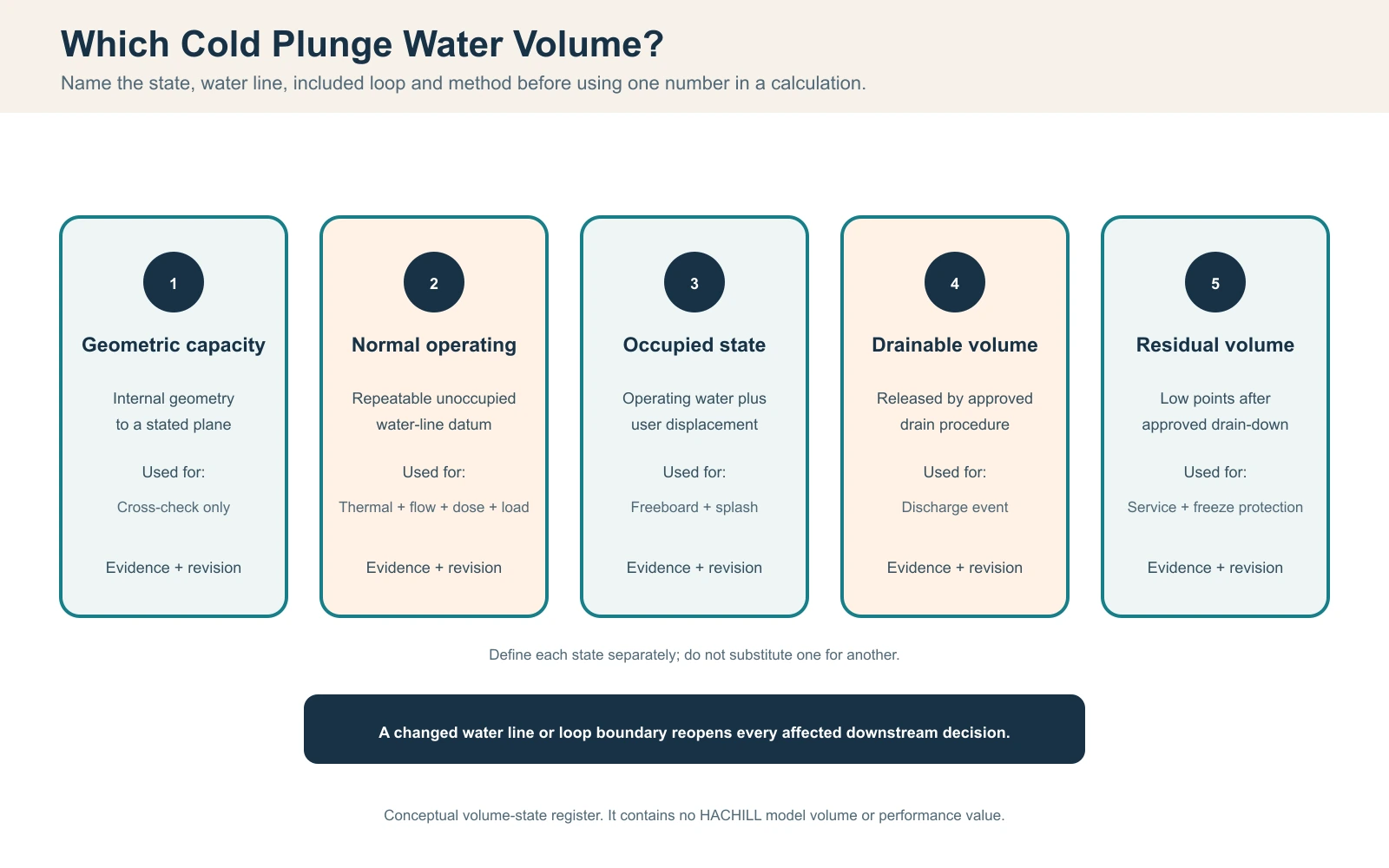
Una inmersión en frío tipo laydown no tiene un único volumen universalmente útil. La capacidad geométrica describe el espacio interno hasta una referencia declarada. El llenado máximo permitido es un límite del producto. El volumen operativo de la tina es el agua en el vaso en la línea de agua normal repetible. El inventario total de agua en circulación puede ser mayor cuando las mangueras externas, los filtros, los intercambiadores de calor o un tanque de amortiguación permanecen llenos durante el funcionamiento. El desplazamiento del usuario es un efecto separado del estado ocupado: eleva el nivel del agua y puede provocar desbordamiento o salpicaduras, pero no crea agua adicional a menos que se añada reposición. El volumen drenable es el agua liberada mediante el procedimiento de drenaje aprobado, mientras que el volumen residual permanece en puntos bajos o componentes después de ese procedimiento. Cada valor sustenta una decisión diferente.
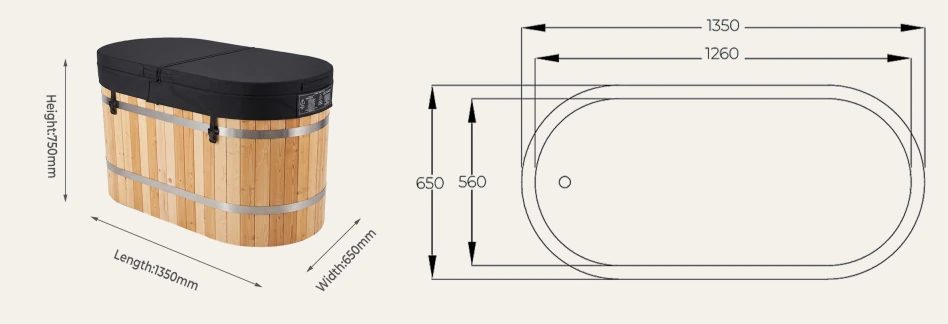
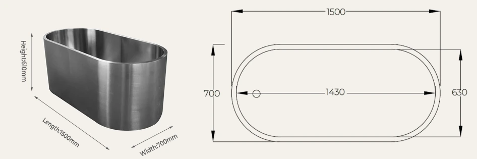
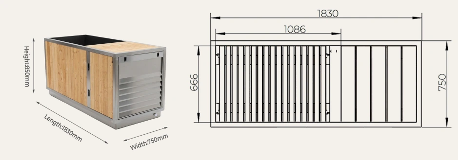
Comience con el modelo, la configuración y el dato de la línea de agua exactos. Registre si los asientos, los escalones, el equipo interno, los tanques de compensación, la tubería externa, los filtros y los intercambiadores de calor están dentro o fuera del límite indicado. No infiera el volumen de funcionamiento a partir de la longitud, el ancho y la altura exteriores: el espesor de las paredes, el aislamiento, los extremos inclinados, los radios, el franco borda y los espacios para equipos pueden hacer que el resultado sea sustancialmente incorrecto. Del mismo modo, no utilice la capacidad de catálogo de un modelo relacionado como evidencia para la configuración pedida.
| Estado de volumen | Dato requerido | Decisión respaldada | No intercambiable con |
|---|---|---|---|
| Capacidad geométrica | Geometría interna aprobada y línea de referencia de llenado | Verificación de diseño | Volumen de funcionamiento normal |
| Llenado máximo permitido | Instrucción y nivel del producto | Límite de rebosadero/borde libre | Nivel de funcionamiento recomendado |
| Volumen de funcionamiento normal | Nivel repetible y configuración exacta | Base térmica, de flujo, de tratamiento y de carga | Envolvente exterior |
| Inventario total de agua en circulación | Volumen de funcionamiento de la tina más los componentes del circuito conectado llenos dentro del límite declarado | Inventario térmico y cálculos a nivel de sistema cuando corresponda | Volumen de funcionamiento solo de la tina |
| Estado ocupado/desplazado | Condición de usuario controlada representativa | Borde libre, salpicaduras y procedimiento de funcionamiento | Llenado sin ocupación |
| Volumen drenable | Procedimiento aprobado de válvula/ruta | Evento de descarga | Inventario completo del sistema |
| Volumen residual | Inspección de puntos bajos y componentes | Protección de servicio y contra heladas | Resto visible de la bañera |
Emita un programa de volumen controlado en lugar de copiar números en documentos térmicos, estructurales y operativos separados. El programa debe mostrar unidades, fuente, método, revisión y estado. Si el nivel de operación o el circuito conectado cambia, los registros dependientes deben identificar si la base de volumen aprobada cambió.
Medir el volumen operativo con un método reproducible
Un contador de llenado calibrado suele ser el método de puesta en marcha más directo cuando su rango de caudal, resolución e instalación son adecuados. Parta del estado de vaciado declarado, cierre o aísle los mismos componentes utilizados en funcionamiento, llene hasta el nivel aprobado y registre el inicio y el final del contador. Si un contador de obra no puede resolver la cantidad de forma fiable, utilice un recipiente de transferencia calibrado adecuado, un método gravimétrico o un cálculo controlado de geometría interna. El método elegido debe coincidir con la precisión de decisión requerida.
Registre la temperatura del agua cuando la conversión de densidad sea relevante, la identidad del contador, el estado de calibración o verificación, la resolución, las lecturas de inicio/fin, el aire atrapado, el estado del circuito conectado y cualquier agua añadida después del cebado. Para un método gravimétrico, convierta la masa medida en volumen utilizando una densidad del agua adecuada para la condición declarada. Para la geometría, divida los interiores irregulares en formas justificadas y documente radios, pendientes, asientos y el plano de la línea de flotación. Nunca oculte una geometría estimada dentro de un valor etiquetado como medido.
| Registro | Cómo se obtuvo | Control de calidad | Uso dependiente |
|---|---|---|---|
| Configuración exacta | Registro aprobado de modelo/pedido | Revisión y circuito incluido | Todas las decisiones posteriores |
| Nivel de referencia de la línea de agua | Nivel o dimensión marcada desde la referencia | Foto más medición | Llenado repetible |
| Identidad del medidor/colección | Serie, rango y resolución | Estado de calibración/verificación en campo | Volumen medido |
| Inicio y fin | Lecturas con marcas de tiempo | Sin reposición no registrada | Cantidad neta llenada |
| Adiciones de cebado | Adiciones medidas por separado | Estado de válvula y bomba registrado | Bucle de operación completo |
| Incertidumbre del método | Estimación del instrumento y del procedimiento | Revisor y límite de aceptación | Decisión de cambio/reprueba |
Repita el llenado cuando el primer resultado no sea creíble, el método haya cambiado durante la prueba o se haya producido una adición no medida. Conserve ambos resultados y el motivo de la repetición. Reemplazar un registro fallido o incompleto con el número final elimina la evidencia necesaria para resolver una disputa posterior.
Incluya la incertidumbre de medición en la decisión
Un número mostrado no es automáticamente un valor exacto. La resolución del medidor, el estado de calibración, la línea de agua inestable, el aire retenido, el movimiento de la superficie y el agua de cebado no medida contribuyen a la incertidumbre. Exprese la medición como un resultado con una incertidumbre o tolerancia justificada y apropiada para el proyecto. Evite la precisión falsa, como informar un volumen de un recipiente grande con una fracción de litro cuando el nivel de llenado varía varios milímetros.
Utilice una banda de aceptación establecida antes de la prueba. Si el valor medido está fuera de la banda aprobada, no lo promedie con el número de diseño. Identifique si el modelo, el nivel, el método o el circuito suministrado difieren. Luego realice una revisión de impacto. Una pequeña diferencia porcentual puede ser irrelevante para una decisión y material para una dosis de tratamiento, un límite estructural o una reclamación de capacidad contractual.
| Registro afectado | Pregunta cuando cambia el volumen | Propietario | Evidencia de liberación |
|---|---|---|---|
| Selección térmica | ¿Cambia la aceptación de energía o recuperación? | Ingeniero de proyecto/proveedor | Cálculo revisado o justificación de no impacto |
| Registro hidráulico | ¿Cambia la base de renovación o el punto de funcionamiento? | Diseñador/instalador del sistema | Caudal verificado y tiempo revisado |
| Procedimiento de tratamiento | ¿Siguen siendo correctas las cantidades de dosificación y reposición? | Operador/especialista en agua | Revisión aprobada del procedimiento |
| Base estructural | ¿Se mantiene aceptada la carga operativa en lleno? | Profesional cualificado del proyecto | Revisión por escrito |
| Evento de drenaje | ¿La cantidad/perfil de descarga requiere una nueva prueba? | Equipo de drenaje del proyecto | Registro de evento controlado |
| Especificación comercial | ¿Se omitió algún requisito del pedido? | Comprador/proveedor | Disposición de desviación aprobada |
Convierta el volumen de agua en un requisito de energía del lado del agua
Para un cálculo de cribado, convierta el volumen de agua declarado a masa con m = ρ × V, utilizando unidades coherentes y una densidad del agua adecuada a la temperatura y presión indicadas. El cambio de energía sensible del lado del agua es Q = m × cp × ΔT, donde cp es la capacidad calorífica específica utilizada y ΔT es el cambio entre la temperatura inicial y la temperatura objetivo global del agua. Para una primera aproximación simple, esto describe únicamente el contenido de agua dentro del límite elegido. Por sí solo, no incluye el enfriamiento de la estructura de la tina, la ganancia de calor ambiental, la carga solar, el calor de la bomba, el calor de los usuarios, el ciclado del control u otros componentes, a menos que esos efectos se añadan por separado.
Un ejemplo ilustrativo, no de producto, muestra el método: si el volumen de agua declarado es 0.60 m³, un ingeniero supone una densidad de 997 kg/m³ y una capacidad calorífica específica de 4.186 kJ/(kg·K), y el cambio de temperatura del agua en volumen es de 15 K, la masa de agua es de aproximadamente 598 kg y el cambio de energía ideal del lado del agua es de aproximadamente 37.5 MJ, o 10.4 kWh. Estos son supuestos explícitos del ejemplo, no datos de modelos HACHILL ni un resultado garantizado de pull-down. Para los cálculos del proyecto, use volumen y temperaturas verificados y una fuente aceptada de propiedades del agua, como IAPWS, para la condición relevante.
| Variable | Fuente | Unidades / control | Límite |
|---|---|---|---|
| Volumen de funcionamiento V | Registro medido aprobado | m3 o L convertidos de forma coherente | Base exacta del circuito lleno |
| Densidad rho | Fuente/condición de propiedad aceptada | kg/m3 | Supuesto dependiente de la temperatura declarado |
| Calor específico cp | Fuente de propiedad aceptada | kJ/(kg K) | Composición de agua/mezcla declarada |
| Temperatura inicial del volumen | Sensor calibrado y estado de mezcla | °C | Sin lectura de pared individual |
| Temperatura objetivo del volumen | Requisito operativo aprobado | °C | Tolerancia y estabilización definidas |
| Q calculado | m × cp × ΔT | kJ y energía convertida | Excluye ganancias concurrentes |
El resultado es útil para comparar escenarios de volumen o temperatura y para comprobar si un cálculo de un proveedor utiliza la misma base. No es suficiente para seleccionar un enfriador. La refrigeración útil cambia con la temperatura del agua, la condición ambiente, el flujo, el estado del refrigerante/control y la instalación. La potencia nominal del compresor o la potencia de entrada no es capacidad de refrigeración útil.
Estimar el enfriamiento inicial con refrigeración y ganancia de calor adaptadas a las condiciones
Un primer tiempo de cribado puede dividir la eliminación total de calor requerida por una tasa de refrigeración útil media, pero solo si ambas se refieren a las mismas condiciones y límites. Un mejor método de proyecto utiliza intervalos: para cada intervalo registrado o modelado, calcular la refrigeración útil entregada a esa temperatura del agua, condición ambiente y flujo verificado, restar las ganancias de calor concurrentes y acumular la eliminación neta hasta alcanzar la condición objetivo aceptada. Indicar si el cálculo incluye el recipiente, la tubería conectada y el equipo.
Adquirir la temperatura inicial, objetivo y en serie temporal del agua a granel; la temperatura ambiente de entrada del condensador; el flujo del circuito verificado; los estados de la bomba y del compresor; la posición de la cubierta; la condición solar/de la sala; y las lecturas eléctricas relevantes. La ubicación del sensor y la mezcla son importantes. Un recipiente estratificado puede alcanzar el objetivo cerca de una sonda mientras que el agua a granel representativa no lo ha hecho. El método de aceptación debe definir la estabilización, el intervalo de muestreo y la tolerancia permitida antes de las pruebas.
| Entrada de series temporales | Adquisición | Por qué el volumen lo modifica | Criterio de parada / repetición de prueba |
|---|---|---|---|
| Temperatura del agua a granel | Sensores calibrados con nombre | Define la energía restante del agua | Estado de sensor/mezcla no válido |
| Enfriamiento útil | Datos acordes a la condición o balance medido | Debe eliminar una mayor energía del agua | Solo disponible HP/potencia de entrada |
| Entrada ambiente/condensador | Registrador en la entrada real | Cambia la capacidad disponible y la ganancia | Recirculación de aire o entrada bloqueada |
| Flujo de bucle verificado | Método de campo aprobado | Controla el estado del intercambiador de calor | Por debajo/por encima del límite del equipo |
| Estado de cubierta/solar/habitación | Observación con marca de tiempo | Cambios en ganancia concurrente | La prueba difiere del uso aceptado |
| Estado del compresor/bomba | Registro de control y eléctrico | Separa el tiempo de inactividad de la baja capacidad | Disparo o ciclado inexplicable |
Separar descenso inicial, mantenimiento y recuperación del usuario
El descenso inicial comienza desde una temperatura de llenado declarada y lleva todo el sistema a la banda de operación. La carga de mantenimiento compensa la ganancia de calor mientras el sistema espera. La recuperación del usuario comienza desde el cambio de temperatura y el estado de operación después de una o más sesiones. Aumentar el volumen de agua incrementa la energía inicial del lado del agua, pero también puede aumentar el amortiguamiento térmico: la misma pequeña entrada de calor produce un aumento menor de temperatura del agua a granel inmediato. Eso no garantiza una recuperación más rápida, porque el sistema aún debe eliminar la carga adicional del usuario y ambiental.
Defina el caso de operación comercial con marcas de tiempo de sesión, nivel de agua ocupado, secuencia de usuario, estado de la cubierta, condición de la sala y criterio de recuperación requerido. Mida la temperatura en puntos representativos y conserve los estados de bomba/enfriador. No reemplace la evidencia de sesión pico con un promedio diario de usuarios. El caso controlador puede ser un grupo muy cercano, un relleno de limpieza o una tarde calurosa al aire libre.
| Caso de servicio | Condición inicial | Resultado de aceptación | Efecto del volumen |
|---|---|---|---|
| Enfriamiento inicial | Condiciones de llenado y ambiente | Tiempo para alcanzar la banda objetivo estable | La energía del lado del agua escala con la masa |
| Mantenimiento | Objetivo estable, cobertura/ubicación declarada | Tendencia de temperatura/control | La masa térmica cambia la velocidad de deriva |
| Recuperación para un solo usuario | Estado previo/posterior registrado | Volver a la banda aceptada | Amortiguación y energía para eliminar ambos materiales |
| Secuencia máxima | Patrón de sesión aprobado | Sin deriva/desplazamiento no controlado | Un mayor volumen no sustituye a la capacidad |
| Relleno o reposición | Volumen/temperatura añadidos medidos | Retorno según el plan operativo | El agua añadida cambia la masa y la temperatura |
| Cierre anormal | Fallo o pérdida de circulación | Aislamiento/reapertura segura | El agua fría almacenada no demuestra control |
Utilice el volumen operativo con flujo de bucle verificado
Un tiempo de renovación nominal se puede calcular como t = V / q, donde V es el volumen operativo aprobado y q es el flujo circulante verificado en unidades consistentes. Si 600 L se combinan con un flujo observado de 50 L/min, la renovación aritmética es de 12 minutos. Este resultado ilustrativo no demuestra que cada partícula de agua pase a través del filtro en 12 minutos, ni establece una renovación requerida para una jurisdicción o aplicación específica.
El flujo real del bucle depende del punto de operación de la bomba, las pérdidas en tuberías y mangueras, los accesorios, el estado del filtro, el intercambiador de calor y las posiciones de las válvulas. La distribución del flujo dentro del recipiente puede dejar caminos de cortocircuito o zonas de bajo movimiento incluso cuando el flujo medido en la línea es adecuado. Verifique el flujo con un método aprobado en las condiciones finales de filtro limpio y cargado representativo. Registre la velocidad de la bomba, las válvulas, el estado del aire, la ubicación del instrumento y la incertidumbre.
| Entrada / verificación | Evidencia | Decisión | Limitación |
|---|---|---|---|
| Volumen operativo | Programa de volumen aprobado | Base de renovación | Debe incluir el límite de circuito declarado |
| Caudal del circuito | Medición en campo condicionada al contexto | Renovación aritmética/intercambiador de calor | El instrumento y la ubicación son determinantes |
| Punto de funcionamiento de la bomba | Curva más evidencia del sistema instalado | Caudal/altura disponibles | El máximo de la placa de características no es el punto de servicio |
| Estado del filtro | Pruebas de carga limpias y aceptadas | Rango de caudal y disparador de mantenimiento | Una lectura limpia es incompleta |
| Estado de aire/cebado | Registro visual, de presión y de funcionamiento | Repetibilidad y protección de la bomba | La alarma de flujo por sí sola puede no diagnosticar la causa |
| Distribución en el recipiente | Método de trazador/temperatura/inspección | Revisión de cortocircuito y zonas muertas | El flujo de línea no puede probar la uniformidad |
Mantenga los Registros de Tratamiento y Reemplazo de Agua en la Misma Base de Volumen
El volumen de agua es una entrada para muchos cálculos de dosificación, reposición y controlador, pero no existe una concentración universal de desinfectante ni un programa de tratamiento para cada inmersión en frío. El método requerido depende del equipo exacto, la fuente de agua, la carga de usuarios, el sistema químico o de tratamiento complementario, los materiales, el procedimiento operativo y las reglas que se aplican a la instalación. Para recintos acuáticos públicos de EE. UU., el Model Aquatic Health Code de los CDC es una guía modelo, no una regla que se aplique automáticamente en todas partes, y un proyecto debe confirmar si la autoridad local clasifica la instalación dentro de ese alcance. El manual del producto aprobado, el plan cualificado de tratamiento del agua y los requisitos de la autoridad aplicable tienen prioridad.
Documente el volumen utilizado por los controladores, alimentadores y procedimientos escritos. Una falla común ocurre cuando el operador usa la capacidad nominal mientras la puesta en marcha usa un nivel operativo más bajo. El cálculo de la dosis, el porcentaje de reposición y el registro se refieren entonces a cantidades diferentes. Si el desplazamiento del usuario causa un desbordamiento rutinario, el agua de reposición medida también puede cambiar la química y la carga térmica. Registre las adiciones, los eventos de drenaje/relleno y el nivel de agua en el momento del muestreo.
| Registro | Relación de volumen | Entrada responsable | Disparador de cambio |
|---|---|---|---|
| Base de cálculo del tratamiento | Volumen operativo aprobado | Autoridad/operador de tratamiento de agua | Cambios de nivel o de bucle conectado |
| Configuración del controlador/alimentador | Volumen del sistema configurado cuando corresponda | Rol de puesta en marcha cualificado | Revisión del controlador o del equipo |
| Agua de reposición | Cantidad añadida medida | Registro del operador | Investigación de desbordamiento, evaporación o fuga |
| Desagüe/relleno | Volumen retirado/añadido medido | Registro del operador/servicio | Cambios en el procedimiento o en las rutas de descarga |
| Contexto de la muestra | Nivel, tiempo y estado de funcionamiento | Operador capacitado | El resultado no se puede comparar |
| Límite del material | Exposición a química/limpiador | Proveedor más operador | Problema de corrosión, acabado o sello |
Detenga el uso de acuerdo con el procedimiento operativo aprobado cuando no se pueda verificar el control de agua requerido, cuando ocurra un evento de contaminación activa o cuando una pérdida de volumen inexplicable sugiera una fuga. La reapertura requiere la causa, la acción correctiva y los registros de aprobación aplicables, no solo la restauración del nivel mostrado.
Convierta el volumen en masa operativa llena
La masa de agua es aproximadamente la densidad multiplicada por el volumen; la base de carga del proyecto luego agrega el producto vacío, los usuarios, el equipo incluido, los accesorios y cualquier componente soportado por separado. Indique si el resultado es masa o fuerza y no etiquete los kilogramos como carga de piso. El profesional estructural o de proyecto calificado determina las reacciones, la distribución de carga, las consideraciones dinámicas o sísmicas y si la estructura existente es adecuada.
Use la huella de soporte exacta, el marco o la disposición de los pies de un dibujo aprobado. Dividir el peso total por el área de planta exterior puede ocultar reacciones concentradas. Registre si el enfriador, los escalones, la cubierta, el tanque de equilibrio o la plataforma de servicio comparten el mismo soporte. La nivelación y el soporte continuo también pueden ser requisitos de instalación del producto incluso cuando la capacidad nominal parece adecuada.
| Componente | Fuente de evidencia | Condición incluida | Pregunta del revisor |
|---|---|---|---|
| Producto vacío | Registro aprobado de modelo/pedido | Configuración exacta | ¿Incluye equipo de fábrica? |
| Agua operativa | Volumen de operación aprobado por rho x | Temperatura/base declarada | ¿Se incluye el agua del circuito cerrado? |
| Usuarios | Caso de operación aprobado | Ocupación máxima aceptada | ¿Dónde se aplica la carga? |
| Accesorios/escalones/cubierta | Alcance aprobado de suministro/obra | Posición de operación/almacenamiento | ¿Soporte igual o separado? |
| Reacciones de apoyo | Plano exacto de base/patas | Condición de instalación nivelada | ¿Concentrada o distribuida? |
| Aceptación del proyecto | Revisión estructural cualificada | Sitio y normas aplicables | ¿Qué cambio reabre la aprobación? |
Convertir el volumen drenable en un evento de descarga
El diseño del drenaje requiere tanto cantidad como caudal. El volumen operativo aprobado ayuda a acotar la liberación intencional, pero la cantidad drenable puede diferir porque los componentes conectados y los puntos bajos residuales cambian el inventario. Mida el evento de caudal frente al tiempo bajo la válvula, manguera, elevación y condición de recepción finales. El caudal de descarga promedio observado es igual al volumen descargado medido dividido por el tiempo transcurrido para el intervalo declarado; el caudal por gravedad puede disminuir con el nivel de agua, por lo que el promedio no demuestra el pico.
Esta página traslada el volumen aprobado, el inventario drenable y la configuración instalada a la decisión de drenaje. La guía separada Guía de planificación de drenaje para inmersión en frío en posición laydown abarca con más detalle la trayectoria de recepción, la construcción de la zona húmeda, la condensación, el destino de descarga y la aceptación de eventos de mojado. Un mayor volumen de agua no requiere automáticamente una salida de producto más grande, y un desagüe de suelo visible no prueba que el sistema receptor pueda aceptar el evento de descarga determinante.
| Entrada transferida | Adquisición | Uso de la ruta de recepción | Condición de mantenimiento |
|---|---|---|---|
| Volumen operativo/drenable | Programa de volumen medido y prueba de drenaje | Liberación total planificada | Base o residual desconocido |
| Caudal frente a tiempo | Serie de volumen/nivel cronometrada | Evento de origen rector | Solo se registró el volumen total |
| Válvula/manguera/elevación | Registro exacto del estado instalado | Repetibilidad y pérdida de carga | La ruta temporal difiere |
| Liberaciones de servicio/limpieza | Registro de tarea observada | Eventos pequeños frecuentes | Sin recogida controlada |
| Liberación almacenada anormal | Inventario del sistema y simulacro de respuesta | Entrada de contención/aislamiento | Sin autoridad ni tiempo de respuesta |
| Destino permitido | Aprobación local calificada | Límite de descarga final | Destino/condición del agua abierta |
Controlar el nivel de agua para que los registros de rendimiento sigan siendo comparables
Marque o mida el nivel de operación aprobado con una referencia que sobreviva a la limpieza y el servicio. El operador debe registrar eventos de reposición, desbordamiento por desplazamiento, drenajes parciales intencionales, estado de la cubierta y pérdida de nivel inexplicada. Una tendencia térmica o química no se puede comparar de manera fiable si la masa de agua cambia sin un registro. Los sistemas de llenado automático requieren su propio control, prevención de reflujo y revisión de fallos por parte de personal cualificado.
Defina una banda de operación aceptable en lugar de tratar cualquier nivel visible como correcto. La banda debe preservar el funcionamiento del producto, el cebado hidráulico, el borde libre y la base de cálculo aprobada. Si el nivel queda fuera de ella, siga el procedimiento de parada o corrección específico del modelo. Nunca haga funcionar una bomba, calentador o enfriador en un estado prohibido por su manual.
| Evento | Registro mínimo | Verificación dependiente | Escalamiento |
|---|---|---|---|
| Arranque normal | Nivel/referencia, temperatura, hora | Base de volumen válida | Fuera de la banda aprobada |
| Desbordamiento/salpicadura del usuario | Sesión/estado y reposición | Cambio térmico/tratamiento | Pérdida repetida inesperada |
| Evaporación/reposición | Adición medida y fuente | Química y carga | Tasa anormal |
| Sospecha de fuga | Hora, ubicación, fuentes aisladas | Cierre y diagnóstico | Agua no controlada |
| Drenaje/servicio parcial | Volumen retirado/agregado y motivo | Restablecimiento del procedimiento | Intervención no registrada |
| Cambio de configuración | Pieza/plano/revisión | Todos los cálculos dependientes | Sin control de cambios aprobado |
Grado Volumen Evidencia y Control Revisiones
Para el control de documentos del proyecto, una escala interna práctica de evidencia puede separar los datos medidos de los supuestos de planificación. Las etiquetas A–E a continuación no son un estándar externo de la industria. En este artículo, Grado A significa una medición presenciada y específica de la configuración, utilizando un método identificado y una línea de agua controlada; Grado B significa un registro aprobado del modelo exacto con configuración y revisión declaradas; Grado C significa un cálculo trazable a partir de la geometría interna aprobada; Grado D significa una estimación cualificada para planificación; y Grado E significa una fotografía, una declaración de categoría o una afirmación no documentada que no puede cerrar un requisito numérico.
La calidad de la evidencia no sustituye la aplicabilidad. Una medición de prototipo bien ejecutada puede seguir siendo inadecuada para la unidad pedida si el liner, el equipo interno, la línea de agua o el circuito conectado difieren. Registre el modelo, la configuración, la condición, el método, el instrumento, el testigo, la fecha, la revisión y las limitaciones. Los cambios en la geometría, el equipo interno, la línea de agua, la tubería conectada o la disposición de rebose requieren una revisión de impacto antes de reutilizar el valor anterior.
| Grado | Evidencia | Uso permitido | Límite faltante |
|---|---|---|---|
| A | Medición presenciada de configuración exacta | Puesta en marcha/aceptación del contrato | Solo dentro del método y la condición declarados |
| B | Registro técnico aprobado del modelo exacto | Selección y presentación | Estado de campo aún verificado |
| C | Cálculo geométrico trazable | Verificación de diseño | Volumen irregular/adiciones instaladas |
| D | Estimación calificada con supuestos | Solo planificación temprana | No puede liberar la aceptación dependiente |
| E | Foto, copia de categoría o valor no documentado | Solo orientativo | Sin cierre numérico |
Conserve la evidencia fallida y la sustituida. Marque el estado en lugar de eliminarla. Una disputa puede entonces identificar si el desacuerdo se refiere al instrumento, la línea de agua, la configuración, la definición contractual o la interpretación posterior.
Asigne cada decisión dependiente del volumen
El proveedor debe identificar los registros exactos del producto, los límites del lazo incluidos y las limitaciones específicas del modelo. El comprador/equipo del proyecto debe definir el caso operativo y el requisito de volumen contractual. El instalador registra la configuración final y respalda las pruebas controladas de llenado, flujo y drenaje. El operador mantiene el nivel aprobado y los registros de eventos. Los profesionales locales calificados deciden el cumplimiento estructural, de plomería, eléctrico y de uso público dentro de su autoridad.
| Salida | Propietario principal | Evidencia requerida | Aceptación / liberación |
|---|---|---|---|
| Modelo/configuración exacto | Proveedor/comprador | Pedido y dibujo aprobados | Aprobación técnica del comprador |
| Método de volumen operativo | Proyecto/proveedor | Declaración de método controlado | Testigo designado |
| Resultado de volumen en campo | Rol del instalador/puesta en marcha | Lecturas, nivel, instrumento, condición | Aceptación del proyecto |
| Impacto térmico/hidráulico | Diseñador del sistema/proveedor | Cálculo y prueba revisados | Autoridad técnica |
| Base de carga llenada | Fiesta estructural del proyecto | Programa de masas y soportes | Aprobación cualificada del proyecto |
| Operación de tratamiento/nivel | Operador/especialista en agua | Procedimiento y registros aprobados | Autoridad operativa |
| Destino del drenaje | Proyecto/autoridad local | Registro de diseño y permisos | Autoridad competente |
| Desviación/reensayo | Responsable designado del problema | Causa, cambio y evidencia de superación | Autoridad de liberación original |
Sustituya asignaciones vagas como “por otros” por una organización o función nombrada y la etapa correspondiente. HACHILL puede aclarar la configuración exacta suministrada y revisar un resumen de volumen a nivel de modelo cuando se proporcionen el producto seleccionado y los datos del proyecto; no sustituye el diseño estructural, de fontanería o de salud pública local.
Aceptar documentos, volumen, pruebas dependientes y apertura por separado
La aceptación de documentos cierra la configuración exacta, la definición de la línea de agua, el método, los instrumentos y la tolerancia preacordada. La aceptación de recepción confirma la identidad y el alcance suministrado visible. La aceptación de volumen de llenado registra el resultado presenciado. Las aceptaciones térmica, hidráulica, de tratamiento, de carga y de drenaje permanecen separadas porque cada una tiene métodos y autoridades competentes diferentes. La apertura se mantiene hasta que se complete cada liberación aplicable.
Cuando una prueba falla, conserve las lecturas originales, el nivel de agua, el estado de los instrumentos, las fotografías, las marcas de tiempo, la configuración y los testigos. Identifique la causa antes de cambiar múltiples variables. Registre la acción correctiva y determine qué aprobaciones dependientes se vieron afectadas. Repita la prueba fallida bajo el mismo límite declarado a menos que se revise el método aprobado; si se revisa, explique por qué los resultados no son directamente comparables.
| Etapa | Evidencia de aprobación | Condición de retención / parada | Repetición de prueba controlada |
|---|---|---|---|
| Documento | Base exacta, método, tolerancia y funciones | Modelo/nivel/método abierto | Reemisión de registro aprobado |
| Recepción | Identidad, configuración y revisión de documento | Discrepancia o daño | Disposición y luego reinspección |
| Volumen de llenado | Resultado presenciado dentro del límite aprobado | Adición no controlada o resultado fuera de rango | Repetir después de la corrección de la causa |
| Térmico/caudal | Registros de paso vinculados a condiciones | Sensores, caudal o estado operativo no válidos | Restaurar la condición declarada |
| Carga/drenaje | Registro de aceptación cualificada y evento de humectación | Vía de soporte o recepción abierta | Revisión/reprueba cualificada |
| Apertura | Todos los pasos aplicables y el procedimiento del operador | Fuga, agua no controlada, acceso inseguro o falta de autorización | Liberación específica por causa |
No sobrescriba un registro fallido con la reprueba aprobada. Vincule ambos mediante un número de incidencia y un registro de cambios. Las disputas contractuales deben comparar la definición aceptada de volumen, la configuración exacta, el método, la tolerancia y el bucle incluido antes de discutir sobre un número aislado.
Emitir una hoja de datos de volumen de agua normalizado
Envíe a cada proveedor la misma base: aplicación, modelo exacto o geometría requerida, definiciones de línea de agua normal y máxima, estado de volumen solicitado, límite del bucle conectado, temperaturas inicial y objetivo, criterios de enfriamiento y recuperación, rango de diseño ambiental, patrón de uso, voltaje/frecuencia, alcance de circulación y tratamiento, responsabilidad de carga llena, ruta de drenaje, grado de evidencia, testigo de prueba y mercado de destino. Marque las incógnitas como abiertas.
| Campo de RFQ | Por qué se requiere | Respuesta del proveedor | Etapa de cierre |
|---|---|---|---|
| Estado de volumen y datum | Evita confusión entre nominal y operativo | Valor exacto, método y revisión | Presentación técnica |
| Límite del sistema incluido | Define el inventario de tuberías/filtros | Componentes incluidos/excluidos | Normalización de ofertas |
| Condiciones térmicas | Conecta la masa con el enfriamiento útil | Base de rendimiento vinculada a condiciones | Plan de selección/pruebas |
| Alcance de flujo/tratamiento | Define los registros de entrega y operación | Rango de operación e interfaces | Coordinación del sistema |
| Datos de masa/soporte | Transfiere entradas de carga llena | Masa vacía exacta/dibujo base | Revisión del proyecto |
| Límite de drenaje/servicio | Controla la liberación de agua | Conexión, procedimiento y alcance | Coordinación de instalación |
| Evidencia/aceptación | Hace afirmaciones comparables | Ruta de documentación, verificación y repetición de pruebas | Puertas de PO/apertura |
Una cotización no es técnicamente comparable si un proveedor indica la capacidad nominal, otro el volumen operativo y un tercero incluye tuberías externas sin mencionarlo. Normalice estas definiciones antes de comparar precio o plazo de entrega.
Preguntas frecuentes
¿Se puede calcular el volumen de agua de la bañera de inmersión en frío a partir de las dimensiones exteriores?
No de forma fiable. Las dimensiones exteriores incluyen paredes, aislamiento, pendientes, radios y espacios para el equipo. Utilice un volumen operativo aprobado del modelo exacto o una medición controlada vinculada a la configuración final y a la línea de agua de referencia.
¿El doble de volumen de agua requiere un enfriador del doble de tamaño?
No existe una proporción fija para seleccionar el sistema completo. La energía de descenso de temperatura del lado del agua aumenta con la masa para el mismo cambio de temperatura, pero el tiempo requerido, la refrigeración útil acorde a las condiciones, la ganancia ambiental, el aislamiento, la cubierta, el caudal, la lógica de control y la recuperación del usuario también afectan la selección.
¿Cómo debe verificarse el volumen de funcionamiento de la bañera de inmersión en frío?
Utilice un medidor de llenado calibrado adecuado, un método gravimétrico o un cálculo controlado de geometría interna. Registre la configuración exacta, la línea de referencia del nivel de agua, el estado del circuito conectado, la identidad del instrumento, las lecturas, la temperatura cuando sea relevante y la incertidumbre.
¿Más agua mejora la estabilidad de la temperatura?
Una mayor masa térmica puede reducir el cambio inmediato de temperatura en masa ante una pequeña entrada de calor, pero también requiere más energía para el enfriamiento inicial. La carga máxima de usuarios y el calor ambiental aún requieren refrigeración acorde a las condiciones y un caudal verificado.
¿Qué ocurre si el volumen medido difiere del programa del proveedor?
Conserve ambos registros, identifique si la configuración, el dato, el bucle incluido o el método difieren, y realice una revisión de impacto. Los registros térmicos, hidráulicos, de tratamiento, estructurales, de drenaje y contractuales pueden requerir revisión o una nueva prueba controlada.
Recursos relacionados de HACHILL
Gama de baños de hielo horizontales
Continúe desde el método de volumen hasta las opciones de producto verificadas para instalación.
Planificación del drenaje de inmersión en frío
Llevar el volumen drenable al recorrido de recepción completo y al proceso de zona húmeda.
Ingeniería térmica de baño de agua fría
Utilice el volumen aprobado en el dimensionamiento más amplio del enfriador y el método de prueba.
Soporte de instalación
Coordine las interfaces de producto y sitio que dependen del volumen.
Solicitar presupuesto de proyecto
Enviar el informe normalizado de volumen de agua y operación.
Referencia de bases y límites
Guía de unidades SI del NIST para volumen respalda el uso coherente de metros cúbicos y litros; no define una capacidad de producto ni una línea de agua operativa.
Correlaciones de propiedades del agua líquida de IAPWS proporcionar una base reconocida para las propiedades del agua líquida dependientes de la temperatura cerca de la presión atmosférica; los cálculos del proyecto deben indicar la condición y la base de propiedades utilizadas.
Código de Salud Acuática de Modelo de los CDC es una guía modelo de U.S. para recintos acuáticos públicos. La adopción, el estatus legal y si una instalación de inmersión en frío concreta entra dentro de las normas locales de instalaciones acuáticas deben confirmarse para la jurisdicción.
Resumen del alcance NSF/ANSI/CAN 50 describe categorías de equipos para piscinas, spas, tinas de hidromasaje y otras instalaciones acuáticas recreativas; hacer referencia a ese alcance no constituye una declaración de certificación para ningún producto HACHILL.
Límite técnico: No se declara aquí ningún volumen exacto de modelo HACHILL, tiempo de enfriamiento, caudal de circulación, carga de piso, ajuste de tratamiento o certificación. Rigen los datos aprobados del producto, los manuales, los registros medidos del proyecto y los requisitos locales aplicables. Las decisiones fijas estructurales, de fontanería, eléctricas y de uso público regulado requieren a las partes cualificadas responsables.