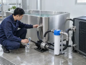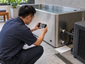
Cold plunge water volume is a controlling engineering input, not just a catalogue capacity. For a laydown tub, the useful number is the water volume tied to a defined operating level and exact configuration; for some calculations, the boundary must also include water held in external pipework, filters, heat exchangers or buffer components.
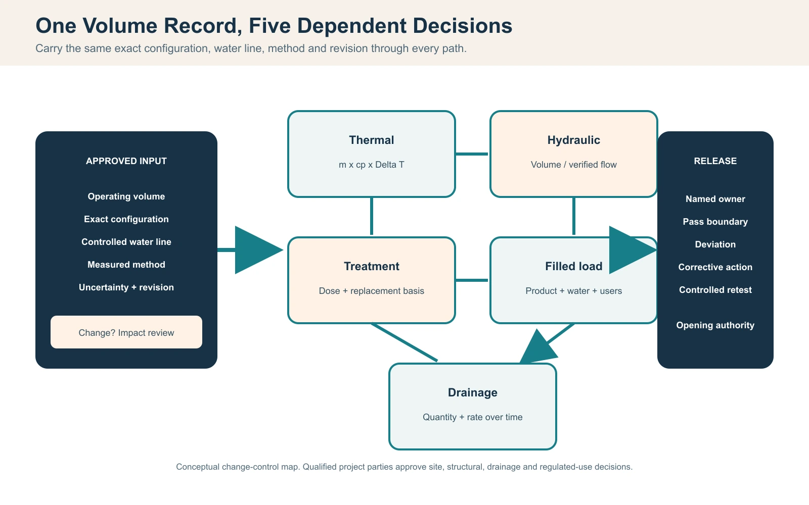
Direct answer: More water increases the water-side energy that must be removed for the same temperature change, changes the arithmetic turnover basis, affects treatment and make-up quantities, increases filled operating mass, and can increase the planned drain-down quantity. Do not infer that volume from outside dimensions or from a related model. Verify the tub operating volume at a repeatable water-line datum, define whether the connected loop is included, record the measurement method and uncertainty, and carry the same approved basis into thermal, hydraulic, structural, treatment and drainage records. If the approved water level, internal geometry or connected loop changes, review each dependent decision before relying on the old result.
Primary input: Verified tub operating volume at a controlled water-line datum, with the connected-loop boundary stated.
Calculation rule: Use declared units and conditions for water energy, useful cooling, flow, mass and discharge calculations.
Release boundary: Recheck dependent decisions when the approved volume basis or configuration changes.
Define Which Cold Plunge Water Volume You Mean
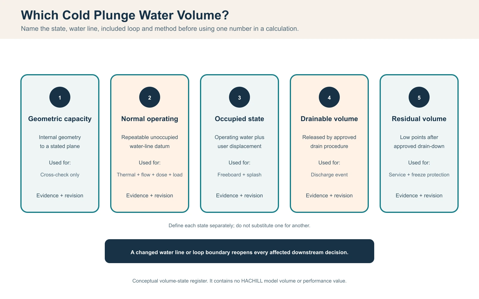
A laydown cold plunge does not have one universally useful volume. Geometric capacity describes internal space to a stated datum. Maximum permitted fill is a product boundary. Tub operating volume is the water in the vessel at the repeatable normal water line. Total circulating water inventory may be larger when external hoses, filters, heat exchangers or a buffer tank remain full during operation. User displacement is a separate occupied-state effect: it raises the water level and may cause overflow or splash, but it does not create extra water unless make-up is added. Drainable volume is the water released through the approved drain procedure, while residual volume remains in low points or components after that procedure. Each value supports a different decision.
Begin with the exact model, configuration and water-line datum. Record whether seats, steps, internal equipment, balance tanks, external pipework, filters and heat exchangers are inside or outside the stated boundary. Do not infer operating volume from outside length, width and height: wall thickness, insulation, sloped ends, radii, freeboard and equipment spaces can make the result materially wrong. Likewise, do not use a catalogue capacity from a related model as evidence for the ordered configuration.
| Volume state | Required datum | Decision supported | Not interchangeable with |
|---|---|---|---|
| Geometric capacity | Approved internal geometry and fill datum | Design cross-check | Normal operating volume |
| Maximum permitted fill | Product instruction and level | Overflow/freeboard boundary | Recommended operating level |
| Normal operating volume | Repeatable level and exact configuration | Thermal, flow, treatment and load basis | External envelope |
| Total circulating water inventory | Tub operating volume plus filled connected-loop components within the declared boundary | Thermal inventory and system-level calculations where applicable | Tub-only operating volume |
| Occupied/displaced state | Representative controlled user condition | Freeboard, splash and operating procedure | Unoccupied fill |
| Drainable volume | Approved valve/route procedure | Discharge event | Complete system inventory |
| Residual volume | Low-point and component inspection | Service and freeze protection | Visible tub remainder |
Issue one controlled volume schedule rather than copying numbers into separate thermal, structural and operating documents. The schedule should show units, source, method, revision and status. If the operating level or connected loop changes, the dependent records must identify whether the approved volume basis changed.
Measure Operating Volume with a Reproducible Method
A calibrated fill meter is usually the most direct commissioning method when its flow range, resolution and installation are appropriate. Start from the declared drained state, close or isolate the same components used in operation, fill to the approved level and record the meter start and finish. If a site meter cannot resolve the quantity reliably, use a suitable calibrated transfer vessel, gravimetric method or controlled internal-geometry calculation. The chosen method must match the required decision accuracy.
Record water temperature where density conversion matters, meter identity, calibration or verification state, resolution, start/finish readings, trapped air, connected-loop state and any water added after priming. For a gravimetric method, convert measured mass to volume using an appropriate water density for the declared condition. For geometry, divide irregular interiors into justified shapes and document radii, slopes, seats and the water-line plane. Never hide estimated geometry inside a value labelled measured.
| Record | How acquired | Quality control | Dependent use |
|---|---|---|---|
| Exact configuration | Approved model/order record | Revision and included loop | All downstream decisions |
| Water-line datum | Marked level or dimension from datum | Photo plus measurement | Repeatable fill |
| Meter/collection identity | Serial, range and resolution | Calibration/field check state | Measured volume |
| Start and finish | Readings with timestamps | No unrecorded make-up | Net filled quantity |
| Priming additions | Separate measured additions | Valve and pump state recorded | Complete operating loop |
| Method uncertainty | Instrument and procedure estimate | Reviewer and acceptance limit | Change/retest decision |
Repeat the fill when the first result is not credible, the method changed during the test or an unmeasured addition occurred. Preserve both results and the reason for repetition. Replacing a failed or incomplete record with the final number removes the evidence needed to resolve a later dispute.
Carry Measurement Uncertainty into the Decision
A displayed number is not automatically an exact value. Meter resolution, calibration state, unstable water line, retained air, surface motion and unmeasured priming water all contribute uncertainty. State the measurement as a result with a justified uncertainty or tolerance appropriate to the project. Avoid false precision such as reporting a large vessel volume to a fraction of a litre when the fill level itself varies by several millimetres.
Use an acceptance band established before the test. If the measured value lies outside the approved band, do not average it with the design number. Identify whether the model, level, method or supplied loop differs. Then perform an impact review. A small percentage difference may be immaterial to one decision and material to a treatment dose, structural limit or contractual capacity claim.
| Affected record | Question when volume changes | Owner | Release evidence |
|---|---|---|---|
| Thermal selection | Does energy or recovery acceptance change? | Supplier/project engineer | Revised calculation or justified no-impact |
| Hydraulic record | Does turnover basis or operating point change? | System designer/installer | Verified flow and revised time |
| Treatment procedure | Are dose and replacement quantities still correct? | Operator/water specialist | Approved procedure revision |
| Structural basis | Does filled operating load remain accepted? | Qualified project professional | Written review |
| Drainage event | Does discharge quantity/profile require retest? | Project drainage team | Controlled event record |
| Commercial specification | Was an order requirement missed? | Buyer/supplier | Approved deviation disposition |
Convert Water Volume into a Water-Side Energy Requirement
For a screening calculation, convert the declared water volume to mass with m = ρ × V, using consistent units and a water density appropriate to the stated temperature and pressure. The sensible water-side energy change is Q = m × cp × ΔT, where cp is the specific heat capacity used and ΔT is the change between initial and target bulk-water temperature. For a simple first pass, this describes the water inventory inside the chosen boundary only. It does not by itself include cooling of the tub structure, ambient heat gain, solar load, pump heat, user heat, control cycling or other components unless those effects are added separately.
An illustrative, non-product example shows the method: if the declared water volume is 0.60 m³, an engineer assumes a density of 997 kg/m³ and a specific heat capacity of 4.186 kJ/(kg·K), and the bulk-water temperature change is 15 K, the water mass is about 598 kg and the ideal water-side energy change is about 37.5 MJ, or 10.4 kWh. These are explicit example assumptions, not HACHILL model data or a guaranteed pull-down result. For project calculations, use verified volume and temperatures and an accepted water-property source such as IAPWS for the relevant condition.
| Variable | Source | Units / control | Boundary |
|---|---|---|---|
| Operating volume V | Approved measured record | m3 or L converted consistently | Exact filled loop basis |
| Density rho | Accepted property source/condition | kg/m3 | Temperature-dependent assumption declared |
| Specific heat cp | Accepted property source | kJ/(kg K) | Water/mixture composition declared |
| Initial bulk temperature | Calibrated sensor and mixing state | °C | No single wall reading |
| Target bulk temperature | Approved operating requirement | °C | Tolerance and stabilization defined |
| Calculated Q | m × cp × ΔT | kJ and converted energy | Excludes concurrent gains |
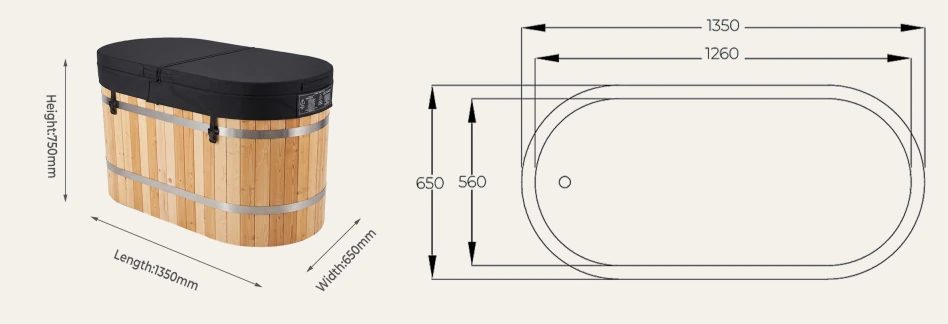
The result is useful for comparing volume or temperature scenarios and checking whether a supplier calculation uses the same basis. It is not enough to select a chiller. Useful cooling changes with water temperature, ambient condition, flow, refrigerant/control state and installation. Nominal compressor horsepower or input power is not useful cooling capacity.
Estimate Pull-Down with Condition-Matched Cooling and Heat Gain
A first screening time can divide total required heat removal by an average useful cooling rate, but only if both refer to the same conditions and boundary. A better project method uses intervals: for each recorded or modelled interval, calculate useful cooling delivered at that water temperature, ambient condition and verified flow, subtract concurrent heat gains, and accumulate net removal until the accepted target condition is reached. State whether the calculation includes the vessel, connected pipework and equipment.
Acquire initial, target and time-series bulk-water temperature; condenser-inlet ambient temperature; verified loop flow; pump and compressor states; cover position; solar/room condition; and relevant electrical readings. Sensor location and mixing matter. A stratified vessel can reach the target near one probe while the representative bulk water has not. The acceptance method should define stabilization, sampling interval and permitted tolerance before testing.
| Time-series input | Acquisition | Why volume changes it | Stop / retest trigger |
|---|---|---|---|
| Bulk-water temperature | Named calibrated sensors | Defines remaining water energy | Sensor/mixing state invalid |
| Useful cooling | Condition-matched data or measured balance | Must remove greater water energy | Only HP/input power available |
| Ambient/condenser inlet | Logger at actual intake | Changes available capacity and gain | Air recirculation or blocked intake |
| Verified loop flow | Approved field method | Controls heat-exchanger condition | Below/above equipment boundary |
| Cover/solar/room state | Timestamped observation | Changes concurrent gain | Test differs from accepted use |
| Compressor/pump state | Control and electrical log | Separates off-time from low capacity | Unexplained trip or cycling |
Separate Initial Pull-Down, Holding and User Recovery
Initial pull-down starts from a declared fill temperature and moves the complete system to the operating band. Holding duty offsets heat gain while the system waits. User recovery begins from the temperature change and operating state after one or more sessions. Increasing water volume raises initial water-side energy, but it can also increase thermal buffer: the same small heat input produces a smaller immediate bulk-water temperature rise. That does not guarantee faster recovery, because the system still must remove the added user and ambient load.
Define the commercial operating case with session timestamps, occupied water level, user sequence, cover state, room condition and required recovery criterion. Measure temperature at representative points and preserve pump/chiller states. Do not replace peak-session evidence with a daily average user count. The controlling case may be a closely spaced group, a cleaning refill or a hot outdoor afternoon.
| Duty case | Start condition | Acceptance output | Volume effect |
|---|---|---|---|
| Initial pull-down | Fill and ambient conditions | Time to stable target band | Water-side energy scales with mass |
| Holding | Stable target, declared cover/site | Temperature/control trend | Thermal mass changes rate of drift |
| Single-user recovery | Recorded pre/post state | Return to accepted band | Buffer and energy to remove both matter |
| Peak sequence | Approved session pattern | No uncontrolled drift/trip | Higher volume is not a substitute for capacity |
| Refill or make-up | Measured added volume/temperature | Return under operating plan | Added water changes mass and temperature |
| Abnormal closure | Fault or lost circulation | Safe isolation/reopening | Stored cold water does not prove control |
Use Operating Volume with Verified Loop Flow
A nominal turnover time can be calculated as t = V / q, where V is approved operating volume and q is verified circulating flow in consistent units. If 600 L is paired with an observed 50 L/min, the arithmetic turnover is 12 minutes. This illustrative result does not prove that every water parcel passes through the filter in 12 minutes, nor does it establish a required turnover for a specific jurisdiction or application.
Actual loop flow depends on the pump operating point, pipe and hose losses, fittings, filter state, heat exchanger and valve positions. Flow distribution inside the vessel can leave short-circuit paths or low-movement zones even when the measured line flow is adequate. Verify flow with an approved method at the final clean and representative loaded filter conditions. Record pump speed, valves, air state, instrument location and uncertainty.
| Input / check | Evidence | Decision | Limitation |
|---|---|---|---|
| Operating volume | Approved volume schedule | Turnover basis | Must include declared loop boundary |
| Loop flow | Condition-linked field measurement | Arithmetic turnover/heat exchanger | Instrument and location matter |
| Pump operating point | Curve plus installed-system evidence | Available flow/head | Nameplate maximum is not duty point |
| Filter state | Clean and accepted loaded tests | Flow range and maintenance trigger | One clean reading is incomplete |
| Air/priming state | Sight, pressure and operating record | Repeatability and pump protection | Flow alarm alone may not diagnose cause |
| Vessel distribution | Tracer/temperature/inspection method | Short circuit and dead-zone review | Line flow cannot prove uniformity |
Keep Treatment and Water-Replacement Records on the Same Volume Basis
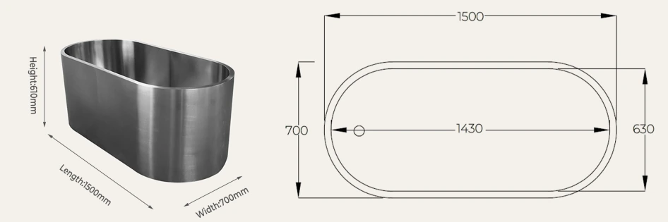
Water volume is an input to many dosing, replacement and controller calculations, but there is no universal sanitizer concentration or treatment schedule for every cold plunge. The required method depends on the exact equipment, water source, user load, chemical or supplemental-treatment system, materials, operating procedure and the rules that apply to the facility. For U.S. public aquatic venues, the CDC Model Aquatic Health Code is model guidance rather than a rule that automatically applies everywhere, and a project must confirm whether the local authority classifies the installation within that scope. The approved product manual, qualified water-treatment plan and applicable authority requirements take priority.
Document the volume used by controllers, feeders and written procedures. A common failure occurs when the operator uses nominal capacity while commissioning uses a lower operating level. The dose calculation, make-up percentage and record then refer to different quantities. If user displacement causes routine overflow, measured make-up water can also change chemistry and thermal load. Record additions, drain/refill events and the water level at sampling.
| Record | Volume relationship | Responsible input | Change trigger |
|---|---|---|---|
| Treatment calculation basis | Approved operating volume | Water-treatment authority/operator | Level or connected loop changes |
| Controller/feeder setup | Configured system volume where applicable | Qualified commissioning role | Controller or equipment revision |
| Make-up water | Measured added quantity | Operator log | Overflow, evaporation or leak investigation |
| Drain/refill | Measured removed/added volume | Operator/service record | Procedure or discharge route changes |
| Sample context | Level, time and operating state | Trained operator | Result cannot be compared |
| Material boundary | Chemistry/cleaner exposure | Supplier plus operator | Corrosion, finish or seal issue |
Stop use according to the approved operating procedure when required water control cannot be verified, when an active contamination event occurs or when an unexplained loss of volume suggests leakage. Reopening requires the cause, corrective action and applicable passing records, not only restoration of the displayed level.
Translate Volume into Filled Operating Mass
Water mass is approximately density multiplied by volume; the project load basis then adds empty product, users, included equipment, accessories and any separately supported components. State whether the result is mass or force and do not label kilograms as a floor load. The qualified structural or project professional determines reactions, load distribution, dynamic or seismic considerations and whether the existing structure is adequate.
Use the exact support footprint, frame or feet arrangement from an approved drawing. Dividing total weight by the outside plan area can hide concentrated reactions. Record whether the chiller, steps, cover, balance tank or service platform shares the same support. Levelness and continuous support can also be product installation requirements even when nominal capacity appears adequate.
| Component | Evidence source | Included condition | Reviewer question |
|---|---|---|---|
| Empty product | Approved model/order record | Exact configuration | Does it include factory equipment? |
| Operating water | rho x approved operating volume | Declared temperature/basis | Is connected-loop water included? |
| Users | Approved operating case | Maximum accepted occupancy | Where is the load applied? |
| Accessories/steps/cover | Approved supplied/site scope | Operating/storage position | Same or separate support? |
| Support reactions | Exact base/feet drawing | Level installed condition | Concentrated or distributed? |
| Project acceptance | Qualified structural review | Site and governing rules | What change reopens approval? |
Convert Drainable Volume into a Discharge Event
Drainage design needs both quantity and rate. The approved operating volume helps bound the intentional release, but the drainable amount can differ because connected components and residual low points change the inventory. Measure the rate-versus-time event under the final valve, hose, elevation and receiving condition. Average observed discharge rate equals measured discharged volume divided by elapsed time for the declared interval; gravity rate can fall with water level, so the average does not prove the peak.
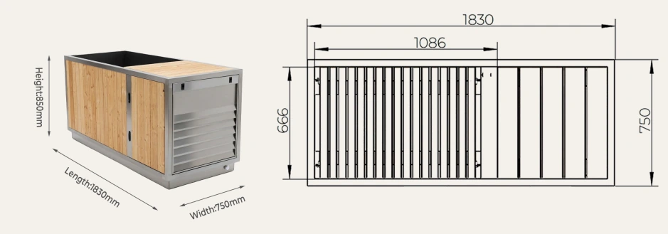
This page transfers the approved volume, drainable inventory and installed configuration into the drainage decision. The separate laydown cold plunge drainage planning guide covers the receiving path, wet-zone construction, condensation, discharge destination and wet-event acceptance in more detail. A larger water volume does not automatically require a larger product outlet, and a visible floor drain does not prove the receiving system can accept the governing discharge event.
| Transferred input | Acquisition | Receiving-path use | Hold condition |
|---|---|---|---|
| Operating/drainable volume | Measured volume schedule and drain trial | Total planned release | Basis or residual unknown |
| Rate-versus-time | Timed volume/level series | Governing source event | Only total volume recorded |
| Valve/hose/elevation | Exact installed-state record | Repeatability and head loss | Temporary route differs |
| Service/cleaning releases | Observed task record | Frequent small events | No controlled collection |
| Abnormal stored release | System inventory and response drill | Containment/isolation input | No authority or response time |
| Permitted destination | Qualified local approval | Final discharge boundary | Destination/water condition open |
Control Water Level so Performance Records Stay Comparable
Mark or measure the approved operating level with a datum that survives cleaning and service. The operator should record make-up events, displacement overflow, intentional partial drains, cover state and unexplained level loss. A thermal or chemistry trend cannot be compared reliably if the water mass changes without a record. Automatic fill systems require their own control, backflow and failure review by qualified parties.
Define an acceptable operating band rather than treating any visible level as correct. The band must preserve product operation, hydraulic priming, freeboard and the approved calculation basis. If level falls outside it, follow the model-specific stop or corrective procedure. Never run a pump, heater or chiller in a state prohibited by its manual.
| Event | Minimum record | Dependent check | Escalation |
|---|---|---|---|
| Normal start | Level/datum, temperature, time | Volume basis valid | Outside approved band |
| User overflow/splash | Session/state and make-up | Thermal/treatment change | Unexpected repeated loss |
| Evaporation/make-up | Measured addition and source | Chemistry and load | Abnormal rate |
| Leak suspected | Time, location, isolated sources | Closure and diagnosis | Uncontrolled water |
| Partial drain/service | Removed/added volume and reason | Procedure reset | Unrecorded intervention |
| Configuration change | Part/drawing/revision | All dependent calculations | No approved change control |
Grade Volume Evidence and Control Revisions
For project document control, a practical internal evidence ladder can separate measured data from planning assumptions. The A–E labels below are not an external industry standard. In this article, Grade A means a witnessed, configuration-specific measurement using an identified method and controlled water line; Grade B means an approved exact-model record with declared configuration and revision; Grade C means a traceable calculation from approved internal geometry; Grade D means a qualified estimate for planning; and Grade E means a photograph, category statement or undocumented claim that cannot close a numerical requirement.
Evidence quality does not replace applicability. A well-executed prototype measurement may still be unsuitable for the ordered unit if the liner, internal equipment, water line or connected loop differs. Record the model, configuration, condition, method, instrument, witness, date, revision and limitations. Changes to geometry, internal equipment, water line, connected pipework or overflow arrangement require an impact review before the old value is reused.
| Grade | Evidence | Permitted use | Missing boundary |
|---|---|---|---|
| A | Witnessed exact-configuration measurement | Commissioning/contract acceptance | Only within declared method and condition |
| B | Approved exact-model technical record | Selection and submittal | Field state still verified |
| C | Traceable geometry calculation | Design cross-check | Irregular volume/installed additions |
| D | Qualified estimate with assumptions | Early planning only | Cannot release dependent acceptance |
| E | Photo, category copy or undocumented value | Orientation only | No numerical closure |
Keep failed and superseded evidence. Mark status rather than deleting it. A dispute can then identify whether the disagreement concerns the instrument, water line, configuration, contract definition or downstream interpretation.
Assign Every Volume-Dependent Decision
The supplier should identify exact product records, included loop boundaries and model-specific limits. The buyer/project team should define the operating case and contractual volume requirement. The installer records the final configuration and supports controlled fill, flow and drainage tests. The operator maintains the approved level and event logs. Qualified local professionals decide structural, plumbing, electrical and public-use compliance within their authority.
| Output | Primary owner | Required evidence | Acceptance / release |
|---|---|---|---|
| Exact model/configuration | Supplier/buyer | Approved order and drawing | Buyer technical approval |
| Operating-volume method | Project/supplier | Controlled method statement | Named witness |
| Field volume result | Installer/commissioning role | Readings, level, instrument, condition | Project acceptance |
| Thermal/hydraulic impact | System designer/supplier | Revised calculation and test | Technical authority |
| Filled-load basis | Project structural party | Mass and support schedule | Qualified project approval |
| Treatment/level operation | Operator/water specialist | Approved procedure and logs | Operating authority |
| Drainage destination | Project/local authority | Design and permission record | Authority having jurisdiction |
| Deviation/retest | Named issue owner | Cause, change and passing evidence | Original release authority |
Replace vague assignments such as “by others” with a named organization or role and due stage. HACHILL can clarify the exact supplied configuration and review a model-level volume brief when the selected product and project inputs are provided; it does not replace local structural, plumbing or public-health design.
Accept Documents, Volume, Dependent Tests and Opening Separately
Document acceptance closes the exact configuration, water-line definition, method, instruments and pre-agreed tolerance. Receiving acceptance confirms identity and visible supplied scope. Fill-volume acceptance records the witnessed result. Thermal, hydraulic, treatment, load and drainage acceptance remain separate because each has different methods and competent authorities. Opening is held until every applicable release is complete.
When a test fails, preserve the original readings, water level, instrument state, photographs, timestamps, configuration and witnesses. Identify the cause before changing multiple variables. Record the corrective action and determine which dependent approvals were affected. Repeat the failed test under the same declared boundary unless the approved method is revised; if revised, explain why results are not directly comparable.
| Gate | Pass evidence | Hold / stop condition | Controlled retest |
|---|---|---|---|
| Document | Exact basis, method, tolerance and roles | Model/level/method open | Reissue approved record |
| Receiving | Identity, configuration and document revision | Mismatch or damage | Disposition then reinspection |
| Fill volume | Witnessed result within approved boundary | Uncontrolled addition or out-of-band result | Repeat after cause correction |
| Thermal/flow | Condition-linked passing records | Invalid sensors, flow or operating state | Restore declared condition |
| Load/drainage | Qualified acceptance and wet-event record | Support or receiving path open | Qualified review/retest |
| Opening | All applicable gates and operator procedure | Leak, uncontrolled water, unsafe access or missing authority | Cause-specific release |
Do not overwrite a failed record with the passing retest. Link both through an issue number and change log. Contract disputes should compare the accepted definition of volume, exact configuration, method, tolerance and included loop before arguing about one isolated number.
Issue a Normalized Water-Volume Data Sheet
Send every supplier the same basis: application, exact model or required geometry, normal and maximum water-line definitions, volume state requested, connected-loop boundary, initial and target temperatures, pull-down and recovery criteria, design ambient range, user pattern, voltage/frequency, circulation and treatment scope, filled-load responsibility, drainage route, evidence grade, test witness and destination market. Mark unknowns open.
| RFQ field | Why required | Supplier response | Closure stage |
|---|---|---|---|
| Volume state and datum | Prevents nominal/operating confusion | Exact value, method and revision | Technical submittal |
| Included system boundary | Defines pipe/filter inventory | Included/excluded components | Bid normalization |
| Thermal conditions | Connects mass to useful cooling | Condition-linked performance basis | Selection/test plan |
| Flow/treatment scope | Defines turnover and operating records | Operating range and interfaces | System coordination |
| Mass/support data | Transfers filled-load inputs | Exact empty mass/base drawing | Project review |
| Drain/service boundary | Controls water release | Connection, procedure and scope | Installation coordination |
| Evidence/acceptance | Makes claims comparable | Document, witness and retest route | PO/opening gates |
A quotation is not technically comparable while one supplier states nominal capacity, another states operating volume and a third includes external pipework without saying so. Normalize these definitions before comparing price or lead time.
Frequently Asked Questions
Can cold plunge water volume be calculated from external dimensions?
Not reliably. External dimensions include walls, insulation, slopes, radii and equipment spaces. Use an approved exact-model operating volume or a controlled measurement tied to the final configuration and water-line datum.
Does twice the water volume require twice the chiller size?
No fixed ratio selects the complete system. Water-side pull-down energy increases with mass for the same temperature change, but required time, condition-matched useful cooling, ambient gain, insulation, cover, flow, control logic and user recovery also affect selection.
How should cold plunge operating volume be verified?
Use a suitable calibrated fill meter, gravimetric method or controlled internal-geometry calculation. Record the exact configuration, water-line datum, connected-loop state, instrument identity, readings, temperature where relevant and uncertainty.
Does more water improve temperature stability?
Greater thermal mass can reduce the immediate bulk-temperature change from a small heat input, but it also requires more energy for initial pull-down. Peak user load and ambient heat still require condition-matched cooling and verified flow.
What happens if measured volume differs from the supplier schedule?
Preserve both records, identify whether configuration, datum, included loop or method differs, and perform an impact review. Thermal, hydraulic, treatment, structural, drainage and contractual records may need revision or controlled retest.
Related HACHILL Resources
Laydown cold plunge range
Continue from the volume method to verified laydown product options.
Cold plunge drainage planning
Carry drainable volume into the complete receiving-path and wet-zone process.
Cold plunge thermal engineering
Use the approved volume in the wider chiller sizing and test method.
Installation support
Coordinate volume-dependent product and site interfaces.
Request a project quotation
Submit the normalized water-volume and operating brief.
Reference Basis and Limits
NIST SI units guidance for volume supports consistent use of cubic metres and litres; it does not define a product capacity or operating water line.
IAPWS liquid-water property correlations provide a recognized basis for temperature-dependent liquid-water properties near atmospheric pressure; project calculations should state the condition and property basis used.
CDC Model Aquatic Health Code is U.S. model guidance for public aquatic venues. Adoption, legal status and whether a particular cold-plunge installation falls within local aquatic-facility rules must be confirmed for the jurisdiction.
NSF/ANSI/CAN 50 scope overview describes equipment categories for pools, spas, hot tubs and other recreational water facilities; referencing that scope is not a certification claim for any HACHILL product.
Technical boundary: No exact HACHILL model volume, pull-down time, circulation flow, floor load, treatment setting or certification is claimed here. Approved product data, manuals, measured project records and applicable local requirements control. Fixed structural, plumbing, electrical and regulated public-use decisions require the responsible qualified parties.