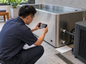
Direct answer: Choose a laydown cold plunge for a spa or recovery center only after the exact configuration matches the intended posture, entry task, peak-use recovery, operating water volume, filled-load inputs, room and delivery route, drainage, cleaning workload and service access. External length or a commercial label is not enough. Clear non-negotiable structural, hydraulic, operating and local-use conditions before scoring price, finish or options.
A defensible selection produces a service brief, model geometry ledger, water/load and thermal records, installed-envelope plan, task-time data, disqualifier register, weighted shortlist, evidence grade, responsibility matrix and acceptance/retest schedule. It does not guarantee comfort, accessibility, medical suitability, certification or field performance outside the recorded boundary.
Start with the Spa or Recovery Service Model
A laydown cold plunge should be selected from the service task, not from shell length or a showroom posture. Record whether the facility operates private appointments, coached recovery sessions, open-access wellness or scheduled team use. The service model controls intended users, peak arrivals, supervision, entry assistance, session turnover, cleaning windows, water-testing duty and closure authority.
Collect real data where a facility already operates. Use timestamped bookings or entry counts, observe queue and reset time, record periods without staff visibility, and time the actual water-test, cleaning and filter tasks. For a new project, label inputs as design value, supplier value, qualified estimate or open. A daily user total hides the short peak that often governs recovery and staffing.
| Input | Acquisition method | Decision affected | Evidence state |
|---|---|---|---|
| Service type | Approved operating concept | Privacy, supervision and room flow | Approved / open |
| Peak arrivals | Timestamped bookings or interval count | Queue, recovery and water duty | Measured / planned |
| Intended posture/users | Service policy plus qualified boundary review | Internal geometry and entry task | Defined / pending |
| Turnover/reset | Timed observation or scripted trial | Booking spacing and labor | Observed / estimated |
| Operating hours | Roster and opening plan | Standby load and maintenance windows | Approved / open |
| Supervision/closure | SOP and sightline walk-through | Stop response and access control | Witnessed / open |
| Local requirements | Qualified project/AHJ review | Public-use, accessibility and regulated gates | Confirmed / pending |
The result is one dated service brief with an owner and revision. When the service changes from coached appointments to open access, the original conclusion no longer controls. Revisit user entry, staffing, water treatment, task frequency and acceptance instead of assuming that the same vessel remains suitable.
Separate Usable Internal Geometry from External and Packed Dimensions
External dimensions establish site and route demand. Packed dimensions establish delivery feasibility. Usable internal length, width, depth, slopes, seat or foot geometry and operating water level establish the intended posture task. These records are related but not interchangeable. Wall thickness, insulation, cladding, sloped ends and equipment compartments can reduce internal space without changing the marketing capacity label.
Obtain the exact model/configuration drawing with defined datums and revision. Record which values are nominal, minimum, maximum or measured. If posture is important, use a controlled dry review or approved mock-up with representative intended users; do not derive a universal body-height limit from one participant. Photographs support orientation but do not prove hidden geometry or scale.
| Field | Preferred evidence | Decision | Boundary |
|---|---|---|---|
| External installed dimensions | Approved model drawing | Room and service coordination | Not internal space |
| Packed dimensions/orientation | Packing and handling drawing | Doors, turns, lifts and removal stage | Include protection |
| Internal usable geometry | Section/plan drawing or controlled sample | Posture, turn and cleaning reach | Exact configuration only |
| Rim/entry geometry | Approved elevation and site detail | Entry, exit and splash route | No accessibility conclusion |
| Operating water level | Manual or controlled record | Buoyancy, displacement and freeboard | Condition specific |
| Ports and service side | Connection drawing | Piping, drain and maintenance | Do not infer from photo |
| Cover/accessories | Included-scope schedule | Storage, handling and interference | Included / optional / local |
| Revision status | Approved document register | Production/site release | Open fields remain open |

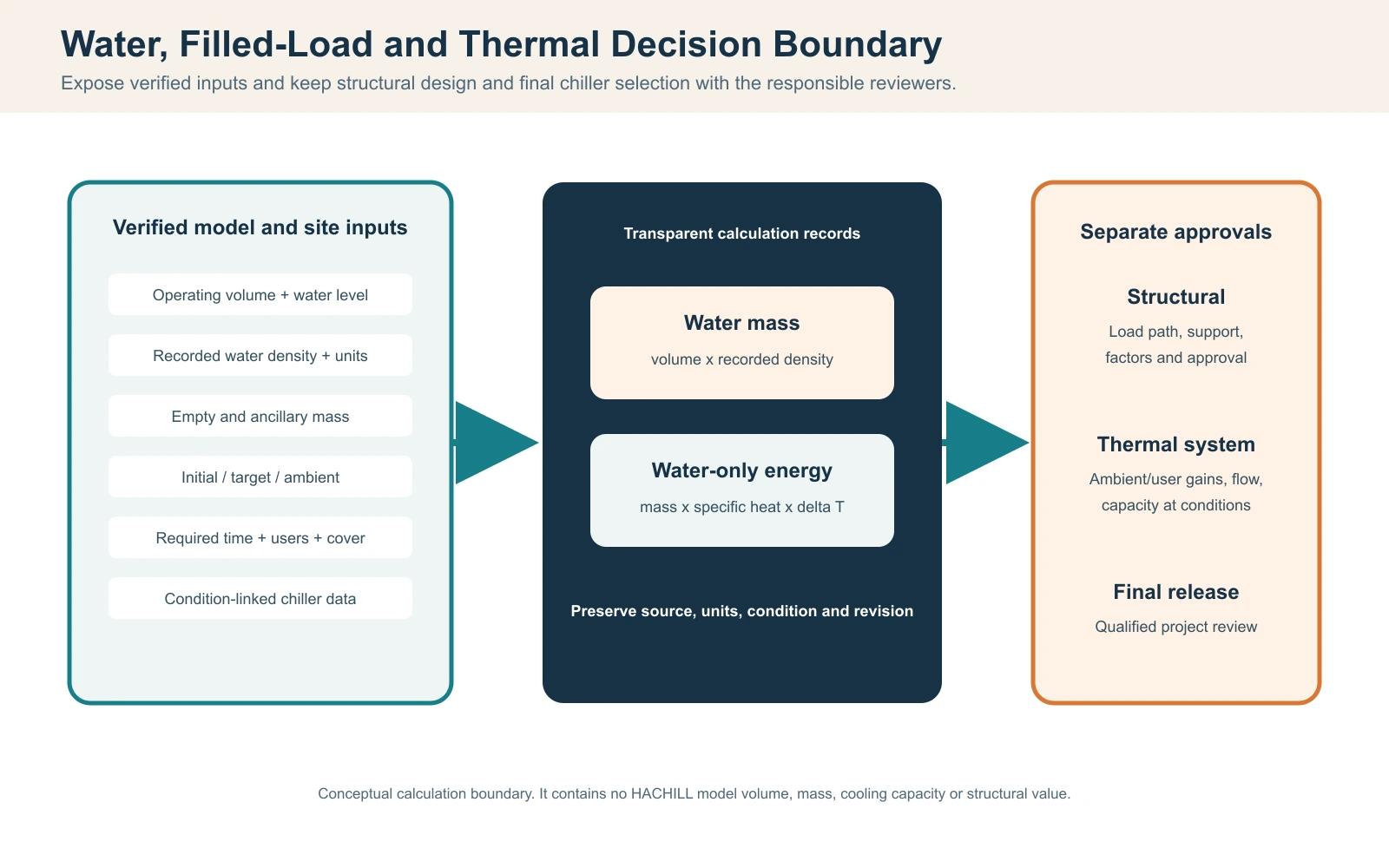
Calculate Water Mass and Expose Every Filled-Load Input
Do not estimate operating volume from the external rectangular box. Use the supplier’s verified operating volume for the exact water level or a controlled fill measurement under an approved method. If a site measures volume, record the meter or container method, starting and ending state, overflow/drain state, units, observer and revision. User displacement changes freeboard and splash but does not replace the controlled operating-volume record.
A transparent calculation is operating water mass = verified operating volume x recorded water density. Keep units consistent and state the assumed water condition. For structural coordination, expose filled-load input = empty equipment mass + operating water mass + confirmed ancillary mass + project-defined user allowance. This is an input ledger, not structural design; support distribution, dynamic effects, safety factors and approval belong to the qualified structural professional.
| Term | Source/method | Calculation use | Owner/status |
|---|---|---|---|
| Operating volume | Exact model record or controlled fill | Water mass and thermal basis | Supplier/commissioning |
| Water density | Recorded engineering assumption and units | Volume-to-mass conversion | Project engineer |
| Empty equipment mass | Approved technical/packing record | Filled-load input | Supplier |
| Ancillary installed mass | Confirmed cover, steps and attached equipment | Installed load completeness | Supplier/site team |
| User allowance | Project-defined design input | Structural operating case | Qualified project team |
| Support/contact area | Approved base/site drawing | Load path review | Structural designer |
| Calculated total | Version-controlled ledger | Site release comparison | Qualified reviewer |
| Change trigger | Model, level or accessory revision | Recalculate affected inputs | Decision owner |
Preserve each source value rather than recording only a total. If water level, cover, attached equipment or configuration changes, the reviewer can identify what must be recalculated. Do not state that load is uniformly distributed unless the approved product and structural design establish that condition.
Define Pull-Down, Recovery and Standby Thermal Duty
A laydown format does not automatically require a larger chiller. Duty depends on verified water mass, initial and target temperatures, required pull-down time, ambient air, solar exposure, surface area, insulation, cover use, user heat input, circulation and the chiller’s actual capacity at the relevant conditions. Name whether the requirement is first pull-down, between-user recovery or continuous temperature maintenance.
The water-only energy boundary is sensible water heat removal = water mass x specific heat x temperature change. Dividing that result by time gives an average water-only rate, not the final equipment selection. Add condition-dependent ambient and user gains and compare them with manufacturer capacity data at the target ambient/water condition. Electrical input power or horsepower wording is not the same as delivered cooling capacity.
| Input | Acquisition | Why it matters | Record |
|---|---|---|---|
| Water mass | Verified volume calculation | Sensible energy | Value, units, source |
| Initial/target temperature | Calibrated or identified instruments | Temperature change | Location and time |
| Required pull-down/recovery | Service brief | Average required rate | Start/end boundary |
| Ambient/solar condition | Site/test observation | Heat gain and condenser duty | Indoor/outdoor, shade |
| Cover/insulation | Exact configuration | Standby and pull-down gain | Open/closed state |
| Users/peak interval | Timestamped service data | Recovery load | Count and sequence |
| Flow/filter state | Commissioning measurements | Heat exchange and sensor validity | Method/instrument |
| Chiller capacity evidence | Model data at stated conditions | Candidate comparison | Capacity, condition, revision |
Commissioning should log time-series water and ambient temperatures, circulation state, cover position, user events and control status. A test at mild indoor conditions cannot prove peak outdoor performance. If a result fails, verify the boundary and instruments before declaring the chiller undersized.
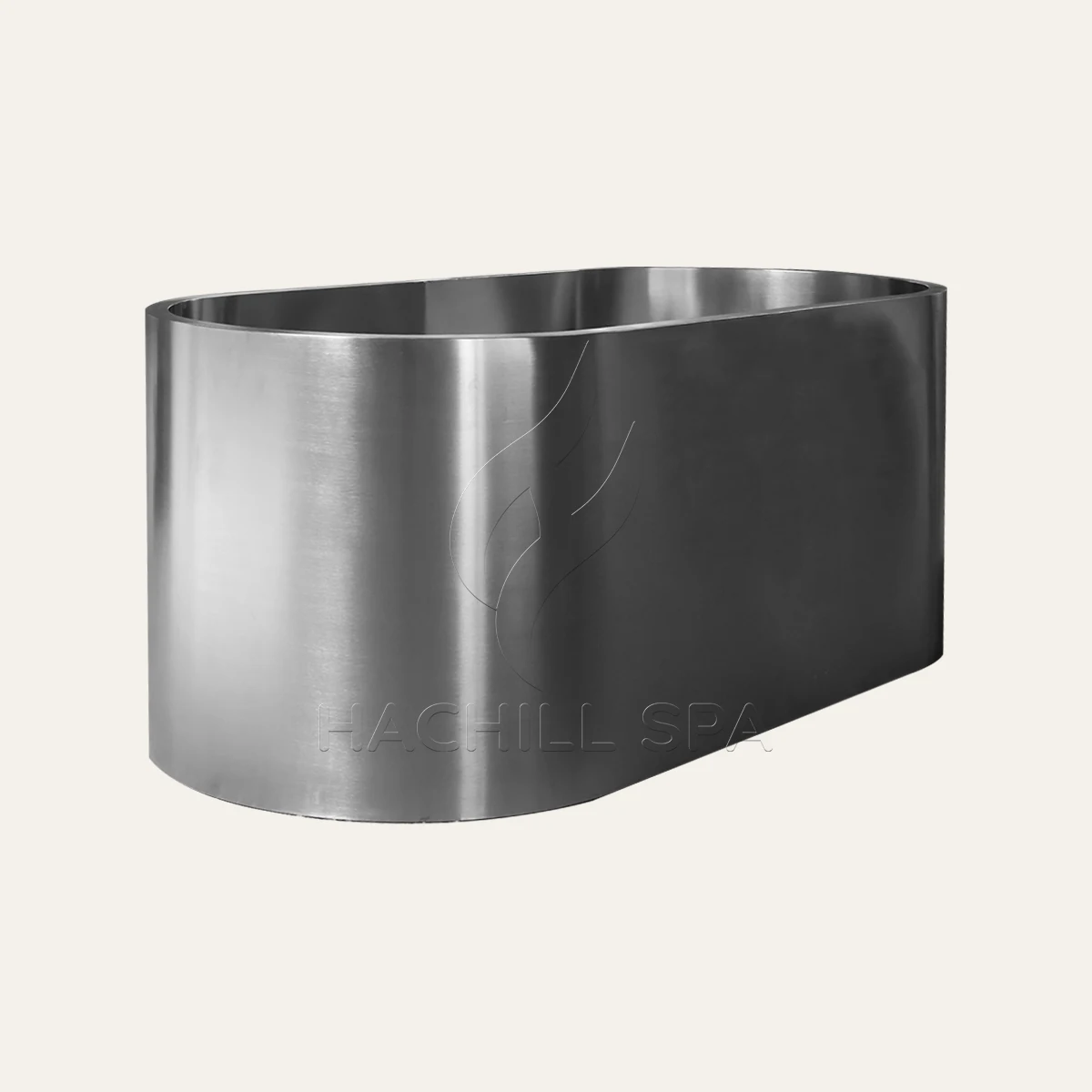
Coordinate Circulation, Treatment, Sampling, Drain and Cleaning Access
Water quality and temperature depend on the complete loop, not on isolated components. Record tub ports, pipe size, equivalent length, fittings, valves, pump curve, filter pressure loss, treatment equipment, sampling point, drain connection, air removal and chiller flow requirements. The operating point occurs where the pump and installed-system curves intersect; a pump’s maximum flow is not the operating flow.
Review whether circulation reaches the intended water volume without inaccessible low-flow or cleaning zones. Do not infer hydraulic performance from port photographs. For shared use, filtration, treatment, chemistry, cleaning and local public-health requirements must be coordinated by responsible professionals; an ozone or UV option does not replace the rest of the operating program.
| Interface | Evidence | Acceptance observation | Responsible party |
|---|---|---|---|
| Tub inlet/outlet | Exact connection drawing | Correct identity, orientation and leak state | Supplier/installer |
| Pump/pipe system | Pump and system data | Priming, flow and stable operation | System designer/installer |
| Filter | Pressure-loss/service data | Clean baseline and accessible removal | Supplier/operator |
| Treatment device | Exact model/manual | Enabled, accessible and within approved operation | Supplier/operator |
| Sampling | SOP and point location | Representative repeatable sample | Operator |
| Drain/discharge | Site and product details | Controlled drain-down and legal discharge | Project designer/trade |
| Air removal/freeze | Approved procedure | No trapped-air or freeze exposure | Installer/operator |
| Change control | Revised loop drawing | Affected flow/treatment retested | Decision owners |
Record flow with the approved instrument and method rather than a visual impression. If a filter blocks, a valve changes or a smaller hose is added, the operating point and heat exchange can change. Preserve a clean-system baseline so later faults can be compared with a known condition.
Calculate the Complete Installed and Operating Envelope
A laydown vessel may provide the intended posture but requires room length, approach, exit, cover movement, cleaning reach, drainage, pipework, chiller airflow and component-removal space. Draw these as separate envelopes on the completed room plan. Count overlaps only when the operating procedure ensures that tasks do not conflict.
Use installed station envelope = union of vessel + entry/exit + recovery + cover + cleaning + service + plant + circulation envelopes. This is a geometric union, not a sum of all rectangles. Check elevation and route as well as plan area: packed orientation, corridor turns, lifts, ceiling restrictions and the stage at which packaging can be removed can block delivery even when the final footprint fits.
| Envelope | Source | Active state | Overlap rule |
|---|---|---|---|
| Vessel/support | Approved model/site drawings | Always | No unapproved encroachment |
| Entry/exit/recovery | Controlled user-flow review | Each session | Cannot overlap queue/egress |
| Cover movement/storage | Approved cover method | Open/close | Protect landing and staff task |
| Cleaning reach | Timed task trial/tools | Reset/deep clean | Closure may allow time sharing |
| Service/removal | Manual and replacement path | Maintenance | Enforced closure required |
| Chiller airflow | Exact equipment data | Operation | No furniture/enclosure intrusion |
| Wet circulation/drainage | Project/local plan | Operating/cleaning | Keep route controlled |
| Packed delivery route | Three-dimensional route survey | Receiving | Separate from final footprint |
Measure Cleaning and Operating Workload Before Setting Throughput
Commercial throughput is limited by more than immersion time. The station must accommodate entry, exit, drying, inspection, surface cleaning, water tests, filter or skimming tasks, records and abnormal closure. Measure each task with the actual layout, tools and access. Do not convert a marketing turnover target into an operating claim.
A planning expression is workload minutes per period = sum(event frequency x observed task minutes) + setup + required wait/contact time + records. Keep routine, peak and abnormal events separate. Contact time and passive equipment operation do not always equal labor minutes, but they can still close the station or constrain bookings.
| Task/event | Frequency trigger | Time/data method | Operating consequence |
|---|---|---|---|
| Between-user reset | Each session or approved trigger | Timed actual task | Booking interval |
| Water test/adjustment | SOP/local requirement | Observed test plus records | Staff competence/closure |
| Filter/skimmer task | Pressure/time/condition | Timed access and restoration | Maintenance window |
| Waterline/interior clean | Schedule/condition | Tool and reach trial | Room and drain demand |
| Drain/refill | Planned or contamination response | Controlled volume/time log | Water/discharge downtime |
| Abnormal reading/leak | Stop rule | Incident/diagnostic record | Unplanned closure |
| Reopen check | After correction | Witnessed acceptance step | Authority to reopen |
| Peak staffing | Peak booking interval | Roster versus task demand | Capacity or schedule limit |
Compare the workload with the roster and actual maintenance window. If the only person trained to test water is unavailable during peak hours, the nominal station capacity is not operational capacity. Record the closure and escalation route before opening.
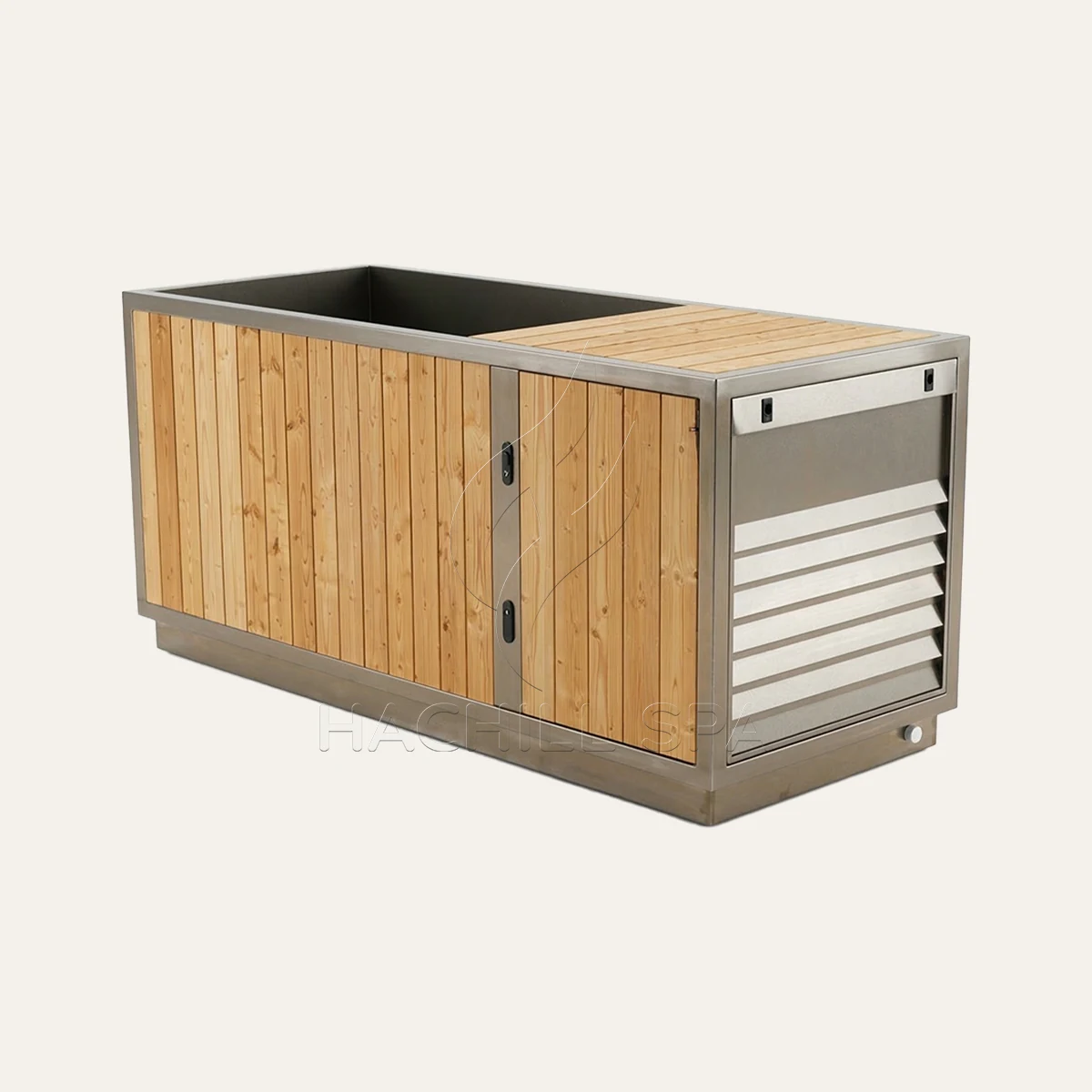
Clear Non-Negotiable Hold Conditions Before Scoring
A weighted comparison cannot average away a critical open interface. Treat unresolved usable geometry, filled-load/support basis, delivery route, user exit, drainage, electrical work, chiller airflow, circulation, treatment, service access or shared-use requirements as hold conditions. A candidate may look attractive on price and finish while remaining unreleasable.
| Hold condition | Evidence needed | Release authority |
|---|---|---|
| Intended posture/entry cannot be validated | Exact geometry and controlled task review | Buyer/operator plus qualified review |
| Filled-load/support basis is open | Approved mass ledger and structural decision | Qualified structural professional |
| Packed route or lifting plan fails | Route survey and approved handling plan | Supplier logistics/site team |
| Drainage/wet route is unresolved | Coordinated drain, floor and discharge plan | Project designer/operator |
| Thermal duty lacks condition-linked evidence | Input/test record and candidate capacity basis | Buyer technical authority |
| Flow/treatment boundary is incomplete | Approved loop and operating responsibility | System designer/operator |
| Cleaning/service components are inaccessible | Completed-layout task trial | Supplier/installer/operator |
| Local shared-use approval remains assumed | Project-specific qualified/AHJ decision | Relevant authority/professional |
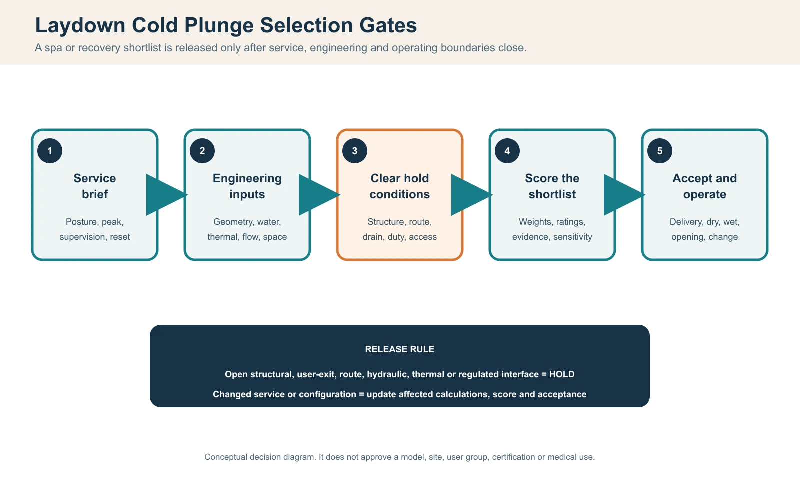
Use a Weighted Shortlist with Disclosed Evidence and Sensitivity
After disqualifiers clear, score criteria that match the service brief: posture task, peak recovery, installed envelope, cleaning workload, service access, evidence confidence and lifecycle responsibility. Set weights before reviewing supplier totals. Use the same evidence rule for each candidate and show deviations instead of rewarding missing information.
One method is weighted shortlist score = sum(weight x rating) / sum(weights). Define the rating scale, retain raw inputs and run a sensitivity check by changing the highest weights within a reasonable project range. If a small weight change reverses the selection, the choice is not robust and should be resolved by evidence or operating priority.
| Criterion | Evidence | Weight rationale | Boundary |
|---|---|---|---|
| Posture/user task | Exact geometry and controlled review | Core service outcome | No universal comfort claim |
| Thermal recovery | Condition-linked data/test | Peak booking duty | Not nominal power |
| Installed/route fit | Union drawing and route survey | Site feasibility | Disqualifier first |
| Cleaning workload | Timed task record | Operating labor/closure | Actual layout |
| Serviceability | Panel/filter/removal trial | Downtime and maintenance | Exact configuration |
| Evidence confidence | Grade and revision register | Procurement uncertainty | Open is not pass |
| Commercial scope | Normalized inclusions/exclusions | Comparable price | No hidden substitution |
| Sensitivity | Alternative reasonable weights | Decision robustness | Escalate unstable result |
Do not publish the score as a HACHILL model ranking. It belongs only to the assessed facility, service model, configuration, evidence revision and decision owner.
Grade Evidence by Model, Condition, Method and Revision
An approved drawing for the exact ordered model is stronger than a category image for geometry. A witnessed test under the target water and ambient boundary is stronger than an unrecorded showroom observation for thermal duty. A certificate or test record must identify scope and model; a standard reference is not evidence that a product is certified.
| Grade | Evidence | Permitted use | Limit |
|---|---|---|---|
| A – controlled | Exact model/configuration, method, condition, witness and revision | Acceptance within recorded boundary | No automatic transfer |
| B – model specific | Approved drawing/manual/test record with clear scope | Design and procurement input | Site/operation still confirm |
| C – analogous | Related model, mock-up or incomplete condition | Risk discovery/provisional planning | Not final release |
| D – illustrative | Marketing image, generic label or unrecorded claim | Orientation only | No dimension/performance conclusion |
| Open | Missing, conflicting or revision-unknown input | Action register | Cannot become an assumption |
Record source, owner, date and affected decision. Preserve superseded and failed records with their status. If a supplier changes a component, material, firmware, port or packing arrangement, identify which calculations, drawings and acceptance tests require repetition.
Assign Product, Site and Operating Responsibility Before Order Release
The buyer/operator defines the service model, user and acceptance boundary. The supplier provides exact product/configuration data, included equipment, manuals and agreed evidence. The project designer coordinates structure, wet area, drainage, route and utilities. Installers build and record the approved arrangement. The operator owns water, cleaning, closure, logs and competence. Qualified professionals and the authority having jurisdiction decide regulated interfaces.
| Decision | Lead | Required output | Witness/approval |
|---|---|---|---|
| Service/user boundary | Buyer/operator | Use pattern, posture, peak and supervision | Qualified reviewers as applicable |
| Product/configuration | Supplier | Model, geometry, mass, ports and included scope | Buyer technical authority |
| Structure/wet-zone/route | Project design team | Coordinated support, drainage and delivery drawings | Qualified local professionals |
| Thermal/hydraulic system | Named system designer | Capacity, flow, treatment and interface record | Commissioning authority |
| Installation | Installer/trades | As-built, leak, flow and electrical records | Project witness |
| Operation | Operator | SOP, testing, cleaning, closure and training | Local review where applicable |
| Acceptance/change | Named decision owner | Deviations, retest and release | Original interface owners |
| Spares/support | Buyer and supplier | Parts list, manuals and escalation route | Procurement/operations |
If one party supplies tub, pump and chiller, still identify drainage, building, electrical, ventilation, water and operating interfaces separately. Commercial convenience does not create an unstated complete-system design.
Accept Documents, Delivery, Wet Performance and Opening Separately
Use distinct gates. Document release verifies the approved model, drawings, evidence and responsibilities. Receiving verifies package, identity, damage, fittings, accessories and revisions before installation. Dry layout verifies support, route, entry, cover, cleaning and service interfaces. Wet commissioning verifies leak status, priming, flow, filter, controls, temperature indication, treatment, drainage and alarms/interlocks under the approved procedure. Opening review verifies staff competence, logs, closure, response and spares.
| Gate | Raw record | Pass boundary | Failure/retest rule |
|---|---|---|---|
| Document/order release | Approved scope/evidence register | Critical inputs and deviations closed | Hold production/site release |
| Receiving | Packing, identity, photos and damage log | Ordered configuration arrives without open damage | Quarantine and preserve custody |
| Dry layout | As-built measurements and task trials | Support, route, entry, cover and access match | Correct cause; repeat dependent tasks |
| Wet commissioning | Leak, flow, treatment, drain and temperature log | Agreed condition-linked criteria met | Stop, diagnose and controlled retest |
| Opening | SOP, training, closure and response drill | Named staff can operate and stop | Do not open unresolved |
| Post-change | Revision impact assessment | Affected evidence repeated/approved | Quarantine changed configuration |
| Dispute | Original requirement, raw data, photos and revisions | Traceable condition and decision | Do not overwrite failed evidence |
Stop use for active leaks, unstable support, sharp or structural damage, suspected electrical exposure, repeated protection trips, loss of required flow, uncontrolled water conditions, blocked drainage or any manual/site stop rule. A retest should change the identified cause while retaining valid controls. Preserve the failed record and corrective revision so supplier, installer and buyer can resolve the actual interface.
Issue a Normalized Laydown RFQ and Acceptance Schedule
Send each supplier the same service brief, room and route drawings, posture task, water/thermal boundary, utilities, drainage, water-treatment plan, cleaning/service requirements, documentation and acceptance gates. Require each response to mark comply, deviation, alternative or open. Compare price only after included, excluded and locally supplied items align.
| RFQ field | Buyer/project input | Supplier response |
|---|---|---|
| Application/service | Spa/recovery model, users, peak and supervision | Declared use limits and conditions |
| Geometry/configuration | Posture task, room and route | Exact model drawings, options and packed data |
| Water/load | Required level/volume evidence and site review | Operating volume, empty mass and interfaces |
| Thermal duty | Initial/target, ambient, timing, users and cover | Condition-linked capacity and controls |
| Hydraulic/treatment | Loop, water-care and responsibility boundary | Ports, flow, filtration/treatment and exclusions |
| Site/service | Drainage, cleaning, cover and maintenance windows | Required envelopes and task access |
| Evidence/acceptance | Documents, witnesses, hold points and retest | Available scope, deviations and method |
| Commercial | Quantity, destination, branding and schedule | Included/excluded scope and change control |
For a HACHILL model-level review, provide these inputs rather than asking which laydown tub is best. The team can review product and manufacturing interfaces while structural, regulated site work, accessibility and operating approval remain with the responsible project parties.
Commercial Laydown Cold Plunge Buying Guide
A model-level selection method for spa service, geometry, thermal duty, installed space, operating workload and acceptance.
Direct answer: For a spa or recovery center, choose a laydown cold plunge by matching the exact model to the intended user posture and entry task, peak-use cooling recovery, verified operating water volume and filled-load inputs, the full installed and delivery envelope, and the facility's drainage, water-care, cleaning, staffing and service plan. Do not select from outside length, a one-person label, chiller horsepower or a generic commercial claim alone. Clear any structural, electrical, drainage, accessibility, public-health or other local-use requirements that apply before comparing finish, options and price.
The buying decision should end with a short list that can be defended against the real operating brief: exact configuration drawings, condition-linked thermal evidence, usable-space and service checks, clear responsibility boundaries, and an acceptance plan. This page explains how to make that selection without turning a buying guide into a substitute for structural design, local approval, detailed chiller engineering, water-treatment procedures or medical guidance.
Start with the Spa or Recovery Service Model
A laydown cold plunge should be selected from the service task, not from shell length or a showroom posture. Record whether the facility operates private appointments, coached recovery sessions, open-access wellness or scheduled team use. The service model controls intended users, peak arrivals, supervision, entry assistance, session turnover, cleaning windows, water-testing duty and closure authority.
Collect real data where a facility already operates. Use timestamped bookings or entry counts, observe queue and reset time, record periods without staff visibility, and time the actual water-test, cleaning and filter tasks. For a new project, label inputs as design value, supplier value, qualified estimate or open. A daily user total hides the short peak that often governs recovery and staffing.
| Input | Acquisition method | Decision affected | Evidence state |
|---|---|---|---|
| Service type | Approved operating concept | Privacy, supervision and room flow | Approved / open |
| Peak arrivals | Timestamped bookings or interval count | Queue, recovery and water duty | Measured / planned |
| Intended posture/users | Service policy plus qualified boundary review | Internal geometry and entry task | Defined / pending |
| Turnover/reset | Timed observation or scripted trial | Booking spacing and labor | Observed / estimated |
| Operating hours | Roster and opening plan | Standby load and maintenance windows | Approved / open |
| Supervision/closure | SOP and sightline walk-through | Stop response and access control | Witnessed / open |
| Local requirements | Qualified project/AHJ review | Public-use, accessibility and regulated gates | Confirmed / pending |
The result is one dated service brief with an owner and revision. When the service changes from coached appointments to open access, the original conclusion no longer controls. Revisit user entry, staffing, water treatment, task frequency and acceptance instead of assuming that the same vessel remains suitable.
Separate Usable Internal Geometry from External and Packed Dimensions
External dimensions establish site and route demand. Packed dimensions establish delivery feasibility. Usable internal length, width, depth, slopes, seat or foot geometry and operating water level establish the intended posture task. These records are related but not interchangeable. Wall thickness, insulation, cladding, sloped ends and equipment compartments can reduce internal space without changing the marketing capacity label.
Obtain the exact model/configuration drawing with defined datums and revision. Record which values are nominal, minimum, maximum or measured. If posture is important, use a controlled dry review or approved mock-up with representative intended users; do not derive a universal body-height limit from one participant. Photographs support orientation but do not prove hidden geometry or scale.
| Field | Preferred evidence | Decision | Boundary |
|---|---|---|---|
| External installed dimensions | Approved model drawing | Room and service coordination | Not internal space |
| Packed dimensions/orientation | Packing and handling drawing | Doors, turns, lifts and removal stage | Include protection |
| Internal usable geometry | Section/plan drawing or controlled sample | Posture, turn and cleaning reach | Exact configuration only |
| Rim/entry geometry | Approved elevation and site detail | Entry, exit and splash route | No accessibility conclusion |
| Operating water level | Manual or controlled record | Buoyancy, displacement and freeboard | Condition specific |
| Ports and service side | Connection drawing | Piping, drain and maintenance | Do not infer from photo |
| Cover/accessories | Included-scope schedule | Storage, handling and interference | Included / optional / local |
| Revision status | Approved document register | Production/site release | Open fields remain open |
Calculate Water Mass and Expose Every Filled-Load Input
Do not estimate operating volume from the external rectangular box. Use the supplier's verified operating volume for the exact water level or a controlled fill measurement under an approved method. If a site measures volume, record the meter or container method, starting and ending state, overflow/drain state, units, observer and revision. User displacement changes freeboard and splash but does not replace the controlled operating-volume record.
A transparent calculation is operating water mass = verified operating volume x recorded water density. Keep units consistent and state the assumed water condition. For structural coordination, expose filled-load input = empty equipment mass + operating water mass + confirmed ancillary mass + project-defined user allowance. This is an input ledger, not structural design; support distribution, dynamic effects, safety factors and approval belong to the qualified structural professional.
| Term | Source/method | Calculation use | Owner/status |
|---|---|---|---|
| Operating volume | Exact model record or controlled fill | Water mass and thermal basis | Supplier/commissioning |
| Water density | Recorded engineering assumption and units | Volume-to-mass conversion | Project engineer |
| Empty equipment mass | Approved technical/packing record | Filled-load input | Supplier |
| Ancillary installed mass | Confirmed cover, steps and attached equipment | Installed load completeness | Supplier/site team |
| User allowance | Project-defined design input | Structural operating case | Qualified project team |
| Support/contact area | Approved base/site drawing | Load path review | Structural designer |
| Calculated total | Version-controlled ledger | Site release comparison | Qualified reviewer |
| Change trigger | Model, level or accessory revision | Recalculate affected inputs | Decision owner |
Preserve each source value rather than recording only a total. If water level, cover, attached equipment or configuration changes, the reviewer can identify what must be recalculated. Do not state that load is uniformly distributed unless the approved product and structural design establish that condition. For a deeper treatment of operating-volume states and their downstream effects, use the laydown cold plunge water-volume guide.
Define Pull-Down, Recovery and Standby Thermal Duty
A laydown format does not automatically require a larger chiller. Duty depends on verified water mass, initial and target temperatures, required pull-down time, ambient air, solar exposure, surface area, insulation, cover use, user heat input, circulation and the chiller's actual capacity at the relevant conditions. Name whether the requirement is first pull-down, between-user recovery or continuous temperature maintenance.
The water-only energy boundary is sensible water heat removal = water mass x specific heat x temperature change. Dividing that result by time gives an average water-only rate, not the final equipment selection. Add condition-dependent ambient and user gains and compare them with manufacturer capacity data at the target ambient/water condition. Electrical input power or horsepower wording is not the same as delivered cooling capacity.
| Input | Acquisition | Why it matters | Record |
|---|---|---|---|
| Water mass | Verified volume calculation | Sensible energy | Value, units, source |
| Initial/target temperature | Calibrated or identified instruments | Temperature change | Location and time |
| Required pull-down/recovery | Service brief | Average required rate | Start/end boundary |
| Ambient/solar condition | Site/test observation | Heat gain and condenser duty | Indoor/outdoor, shade |
| Cover/insulation | Exact configuration | Standby and pull-down gain | Open/closed state |
| Users/peak interval | Timestamped service data | Recovery load | Count and sequence |
| Flow/filter state | Commissioning measurements | Heat exchange and sensor validity | Method/instrument |
| Chiller capacity evidence | Model data at stated conditions | Candidate comparison | Capacity, condition, revision |
Commissioning should log time-series water and ambient temperatures, circulation state, cover position, user events and control status. A test at mild indoor conditions cannot prove peak outdoor performance. If a result fails, verify the boundary and instruments before declaring the chiller undersized. Detailed tub-to-chiller compatibility, pump operating point, controls and commissioning belong in the cold plunge tub and chiller matching guide.
Coordinate Circulation, Treatment, Sampling, Drain and Cleaning Access
Water quality and temperature depend on the complete loop, not on isolated components. Record tub ports, pipe size, equivalent length, fittings, valves, pump curve, filter pressure loss, treatment equipment, sampling point, drain connection, air removal and chiller flow requirements. The operating point occurs where the pump and installed-system curves intersect; a pump's maximum flow is not the operating flow.
Review whether circulation reaches the intended water volume without inaccessible low-flow or cleaning zones. Do not infer hydraulic performance from port photographs. For shared use, filtration, treatment, chemistry, cleaning and local public-health requirements must be coordinated by responsible professionals; an ozone or UV option does not replace the rest of the operating program.
| Interface | Evidence | Acceptance observation | Responsible party |
|---|---|---|---|
| Tub inlet/outlet | Exact connection drawing | Correct identity, orientation and leak state | Supplier/installer |
| Pump/pipe system | Pump and system data | Priming, flow and stable operation | System designer/installer |
| Filter | Pressure-loss/service data | Clean baseline and accessible removal | Supplier/operator |
| Treatment device | Exact model/manual | Enabled, accessible and within approved operation | Supplier/operator |
| Sampling | SOP and point location | Representative repeatable sample | Operator |
| Drain/discharge | Site and product details | Controlled drain-down and legal discharge | Project designer/trade |
| Air removal/freeze | Approved procedure | No trapped-air or freeze exposure | Installer/operator |
| Change control | Revised loop drawing | Affected flow/treatment retested | Decision owners |
Record flow with the approved instrument and method rather than a visual impression. If a filter blocks, a valve changes or a smaller hose is added, the operating point and heat exchange can change. Preserve a clean-system baseline so later faults can be compared with a known condition. Building drainage, wet-zone falls, discharge events and abnormal-release planning should be resolved in the dedicated laydown drainage workflow rather than inferred from the tub outlet.
Calculate the Complete Installed and Operating Envelope
A laydown vessel may provide the intended posture but requires room length, approach, exit, cover movement, cleaning reach, drainage, pipework, chiller airflow and component-removal space. Draw these as separate envelopes on the completed room plan. Count overlaps only when the operating procedure ensures that tasks do not conflict.
Use installed station envelope = union of vessel + entry/exit + recovery + cover + cleaning + service + plant + circulation envelopes. This is a geometric union, not a sum of all rectangles. Check elevation and route as well as plan area: packed orientation, corridor turns, lifts, ceiling restrictions and the stage at which packaging can be removed can block delivery even when the final footprint fits.
| Envelope | Source | Active state | Overlap rule |
|---|---|---|---|
| Vessel/support | Approved model/site drawings | Always | No unapproved encroachment |
| Entry/exit/recovery | Controlled user-flow review | Each session | Cannot overlap queue/egress |
| Cover movement/storage | Approved cover method | Open/close | Protect landing and staff task |
| Cleaning reach | Timed task trial/tools | Reset/deep clean | Closure may allow time sharing |
| Service/removal | Manual and replacement path | Maintenance | Enforced closure required |
| Chiller airflow | Exact equipment data | Operation | No furniture/enclosure intrusion |
| Wet circulation/drainage | Project/local plan | Operating/cleaning | Keep route controlled |
| Packed delivery route | Three-dimensional route survey | Receiving | Separate from final footprint |
Measure Cleaning and Operating Workload Before Setting Throughput
Commercial throughput is limited by more than immersion time. The station must accommodate entry, exit, drying, inspection, surface cleaning, water tests, filter or skimming tasks, records and abnormal closure. Measure each task with the actual layout, tools and access. Do not convert a marketing turnover target into an operating claim.
A planning expression is workload minutes per period = sum(event frequency x observed task minutes) + setup + required wait/contact time + records. Keep routine, peak and abnormal events separate. Contact time and passive equipment operation do not always equal labor minutes, but they can still close the station or constrain bookings.
| Task/event | Frequency trigger | Time/data method | Operating consequence |
|---|---|---|---|
| Between-user reset | Each session or approved trigger | Timed actual task | Booking interval |
| Water test/adjustment | SOP/local requirement | Observed test plus records | Staff competence/closure |
| Filter/skimmer task | Pressure/time/condition | Timed access and restoration | Maintenance window |
| Waterline/interior clean | Schedule/condition | Tool and reach trial | Room and drain demand |
| Drain/refill | Planned or contamination response | Controlled volume/time log | Water/discharge downtime |
| Abnormal reading/leak | Stop rule | Incident/diagnostic record | Unplanned closure |
| Reopen check | After correction | Witnessed acceptance step | Authority to reopen |
| Peak staffing | Peak booking interval | Roster versus task demand | Capacity or schedule limit |
Compare the workload with the roster and actual maintenance window. If the only person trained to test water is unavailable during peak hours, the nominal station capacity is not operational capacity. Record the closure and escalation route before opening.
Clear Non-Negotiable Hold Conditions Before Scoring
A weighted comparison cannot average away a critical open interface. Treat unresolved usable geometry, filled-load/support basis, delivery route, user exit, drainage, electrical work, chiller airflow, circulation, treatment, service access or shared-use requirements as hold conditions. A candidate may look attractive on price and finish while remaining unreleasable.
| Hold condition | Evidence needed | Release authority |
|---|---|---|
| Intended posture/entry cannot be validated | Exact geometry and controlled task review | Buyer/operator plus qualified review |
| Filled-load/support basis is open | Approved mass ledger and structural decision | Qualified structural professional |
| Packed route or lifting plan fails | Route survey and approved handling plan | Supplier logistics/site team |
| Drainage/wet route is unresolved | Coordinated drain, floor and discharge plan | Project designer/operator |
| Thermal duty lacks condition-linked evidence | Input/test record and candidate capacity basis | Buyer technical authority |
| Flow/treatment boundary is incomplete | Approved loop and operating responsibility | System designer/operator |
| Cleaning/service components are inaccessible | Completed-layout task trial | Supplier/installer/operator |
| Local shared-use approval remains assumed | Project-specific qualified/AHJ decision | Relevant authority/professional |
Use a Weighted Shortlist with Disclosed Evidence and Sensitivity
After disqualifiers clear, score criteria that match the service brief: posture task, peak recovery, installed envelope, cleaning workload, service access, evidence confidence and lifecycle responsibility. Set weights before reviewing supplier totals. Use the same evidence rule for each candidate and show deviations instead of rewarding missing information.
One method is weighted shortlist score = sum(weight x rating) / sum(weights). Define the rating scale, retain raw inputs and run a sensitivity check by changing the highest weights within a reasonable project range. If a small weight change reverses the selection, the choice is not robust and should be resolved by evidence or operating priority.
| Criterion | Evidence | Weight rationale | Boundary |
|---|---|---|---|
| Posture/user task | Exact geometry and controlled review | Core service outcome | No universal comfort claim |
| Thermal recovery | Condition-linked data/test | Peak booking duty | Not nominal power |
| Installed/route fit | Union drawing and route survey | Site feasibility | Disqualifier first |
| Cleaning workload | Timed task record | Operating labor/closure | Actual layout |
| Serviceability | Panel/filter/removal trial | Downtime and maintenance | Exact configuration |
| Evidence confidence | Grade and revision register | Procurement uncertainty | Open is not pass |
| Commercial scope | Normalized inclusions/exclusions | Comparable price | No hidden substitution |
| Sensitivity | Alternative reasonable weights | Decision robustness | Escalate unstable result |
Do not publish the score as a HACHILL model ranking. It belongs only to the assessed facility, service model, configuration, evidence revision and decision owner.
Grade Evidence by Model, Condition, Method and Revision
An approved drawing for the exact ordered model is stronger than a category image for geometry. A witnessed test under the target water and ambient boundary is stronger than an unrecorded showroom observation for thermal duty. A certificate or test record must identify scope and model; a standard reference is not evidence that a product is certified.
| Grade | Evidence | Permitted use | Limit |
|---|---|---|---|
| A - controlled | Exact model/configuration, method, condition, witness and revision | Acceptance within recorded boundary | No automatic transfer |
| B - model specific | Approved drawing/manual/test record with clear scope | Design and procurement input | Site/operation still confirm |
| C - analogous | Related model, mock-up or incomplete condition | Risk discovery/provisional planning | Not final release |
| D - illustrative | Marketing image, generic label or unrecorded claim | Orientation only | No dimension/performance conclusion |
| Open | Missing, conflicting or revision-unknown input | Action register | Cannot become an assumption |
Record source, owner, date and affected decision. Preserve superseded and failed records with their status. If a supplier changes a component, material, firmware, port or packing arrangement, identify which calculations, drawings and acceptance tests require repetition.
Assign Product, Site and Operating Responsibility Before Order Release
The buyer/operator defines the service model, user and acceptance boundary. The supplier provides exact product/configuration data, included equipment, manuals and agreed evidence. The project designer coordinates structure, wet area, drainage, route and utilities. Installers build and record the approved arrangement. The operator owns water, cleaning, closure, logs and competence. Qualified professionals and the authority having jurisdiction decide regulated interfaces.
| Decision | Lead | Required output | Witness/approval |
|---|---|---|---|
| Service/user boundary | Buyer/operator | Use pattern, posture, peak and supervision | Qualified reviewers as applicable |
| Product/configuration | Supplier | Model, geometry, mass, ports and included scope | Buyer technical authority |
| Structure/wet-zone/route | Project design team | Coordinated support, drainage and delivery drawings | Qualified local professionals |
| Thermal/hydraulic system | Named system designer | Capacity, flow, treatment and interface record | Commissioning authority |
| Installation | Installer/trades | As-built, leak, flow and electrical records | Project witness |
| Operation | Operator | SOP, testing, cleaning, closure and training | Local review where applicable |
| Acceptance/change | Named decision owner | Deviations, retest and release | Original interface owners |
| Spares/support | Buyer and supplier | Parts list, manuals and escalation route | Procurement/operations |
If one party supplies tub, pump and chiller, still identify drainage, building, electrical, ventilation, water and operating interfaces separately. Commercial convenience does not create an unstated complete-system design.
Accept Documents, Delivery, Wet Performance and Opening Separately
Use distinct gates. Document release verifies the approved model, drawings, evidence and responsibilities. Receiving verifies package, identity, damage, fittings, accessories and revisions before installation. Dry layout verifies support, route, entry, cover, cleaning and service interfaces. Wet commissioning verifies leak status, priming, flow, filter, controls, temperature indication, treatment, drainage and alarms/interlocks under the approved procedure. Opening review verifies staff competence, logs, closure, response and spares.
| Gate | Raw record | Pass boundary | Failure/retest rule |
|---|---|---|---|
| Document/order release | Approved scope/evidence register | Critical inputs and deviations closed | Hold production/site release |
| Receiving | Packing, identity, photos and damage log | Ordered configuration arrives without open damage | Quarantine and preserve custody |
| Dry layout | As-built measurements and task trials | Support, route, entry, cover and access match | Correct cause; repeat dependent tasks |
| Wet commissioning | Leak, flow, treatment, drain and temperature log | Agreed condition-linked criteria met | Stop, diagnose and controlled retest |
| Opening | SOP, training, closure and response drill | Named staff can operate and stop | Do not open unresolved |
| Post-change | Revision impact assessment | Affected evidence repeated/approved | Quarantine changed configuration |
| Dispute | Original requirement, raw data, photos and revisions | Traceable condition and decision | Do not overwrite failed evidence |
Stop use for active leaks, unstable support, sharp or structural damage, suspected electrical exposure, repeated protection trips, loss of required flow, uncontrolled water conditions, blocked drainage or any manual/site stop rule. A retest should change the identified cause while retaining valid controls. Preserve the failed record and corrective revision so supplier, installer and buyer can resolve the actual interface.
Issue a Normalized Laydown RFQ and Acceptance Schedule
Send each supplier the same service brief, room and route drawings, posture task, water/thermal boundary, utilities, drainage, water-treatment plan, cleaning/service requirements, documentation and acceptance gates. Require each response to mark comply, deviation, alternative or open. Compare price only after included, excluded and locally supplied items align.
| RFQ field | Buyer/project input | Supplier response |
|---|---|---|
| Application/service | Spa/recovery model, users, peak and supervision | Declared use limits and conditions |
| Geometry/configuration | Posture task, room and route | Exact model drawings, options and packed data |
| Water/load | Required level/volume evidence and site review | Operating volume, empty mass and interfaces |
| Thermal duty | Initial/target, ambient, timing, users and cover | Condition-linked capacity and controls |
| Hydraulic/treatment | Loop, water-care and responsibility boundary | Ports, flow, filtration/treatment and exclusions |
| Site/service | Drainage, cleaning, cover and maintenance windows | Required envelopes and task access |
| Evidence/acceptance | Documents, witnesses, hold points and retest | Available scope, deviations and method |
| Commercial | Quantity, destination, branding and schedule | Included/excluded scope and change control |
For a HACHILL model-level review, provide these inputs rather than asking which laydown tub is best. The team can review product and manufacturing interfaces while structural, regulated site work, accessibility and operating approval remain with the responsible project parties.
Frequently asked questions
How do spas choose the right laydown cold plunge?
Start with the service model, intended posture, peak users and supervision. Then compare exact internal geometry, operating water volume, filled-load inputs, thermal recovery, circulation/treatment, installed space, cleaning workload, service access, evidence and acceptance. Clear structural, route, drainage, user-exit and regulated hold conditions before scoring price or finish.
Does a laydown cold plunge always need a larger chiller?
No. Chiller duty depends on verified water mass, initial and target temperatures, required pull-down or recovery time, ambient and solar gains, insulation, cover use, circulation and user pattern. Compare delivered cooling capacity at relevant conditions, not format, horsepower wording or electrical input alone.
Which laydown cold plunge dimensions should an RFQ include?
Keep external installed dimensions, packed route dimensions and usable internal geometry separate. Request plan and section drawings, rim and entry geometry, operating water level, ports, service side, cover movement and exact configuration revision. Photographs and one-person capacity wording do not establish these values.
How should filled load be checked for a laydown cold plunge?
Use verified operating volume to calculate water mass, then expose empty equipment mass, confirmed ancillary mass and the project-defined user allowance. Give those inputs and the approved support drawing to a qualified structural professional. A blog calculation does not determine load distribution, safety factors or structural approval.
What should stop a commercial laydown cold plunge from opening?
Do not open with active leaks, unstable support, unresolved electrical protection, inadequate flow, uncontrolled water conditions, blocked drainage, inaccessible required service, untrained staff, an unclosed user-exit issue or any manual/site stop condition. Preserve the failed evidence, correct the identified cause and perform the required controlled retest.
Related HACHILL resources
Laydown cold plunge range
Use the verified category after the service and evidence brief is defined.
Laydown water-volume requirements
Use the dedicated guide for deeper water-mass and system implications.
Commercial cold plunge solutions
Use the verified commercial project route.
Spa and wellness center solutions
Use the application page for a broader facility brief.
Match a cold plunge tub with a chiller
Use the dedicated engineering guide when the shortlist reaches thermal, hydraulic and control compatibility.
Laydown cold plunge drainage planning
Use the installation guide for drain-down events, wet-zone interfaces and discharge-path verification.
Request a project quotation
Send the normalized RFQ and acceptance boundary for review.
Reference basis
- CDC Model Aquatic Health Code - current US model guidance for public aquatic facilities. It is not federal law; adoption and applicability depend on the relevant jurisdiction.
- NSF/ANSI/CAN 50 pool and spa equipment overview - scope reference for circulation, filtration, treatment and related pool/spa equipment. This citation is not a HACHILL product-certification claim.
- OSHA 1910.22 walking-working surfaces - US workplace requirements relevant to employee walking-working surfaces, including wet-process drainage where applicable; it is not a universal patron-space code.
- NFPA 70 / National Electrical Code - US electrical reference used only as a jurisdiction-dependent source context; the adopted edition and exact project requirements must be confirmed locally.
Turn the service brief into a model shortlist
Send HACHILL the service model, intended users and posture, peak interval, room and route drawings, target water and ambient duty, utilities, drainage, treatment plan, cleaning/service constraints, evidence requirements, destination, quantity and branding scope. Unsupported fields can remain open until model-level evidence closes them.
Request a laydown project review