Cold Plunge Engineering Guide
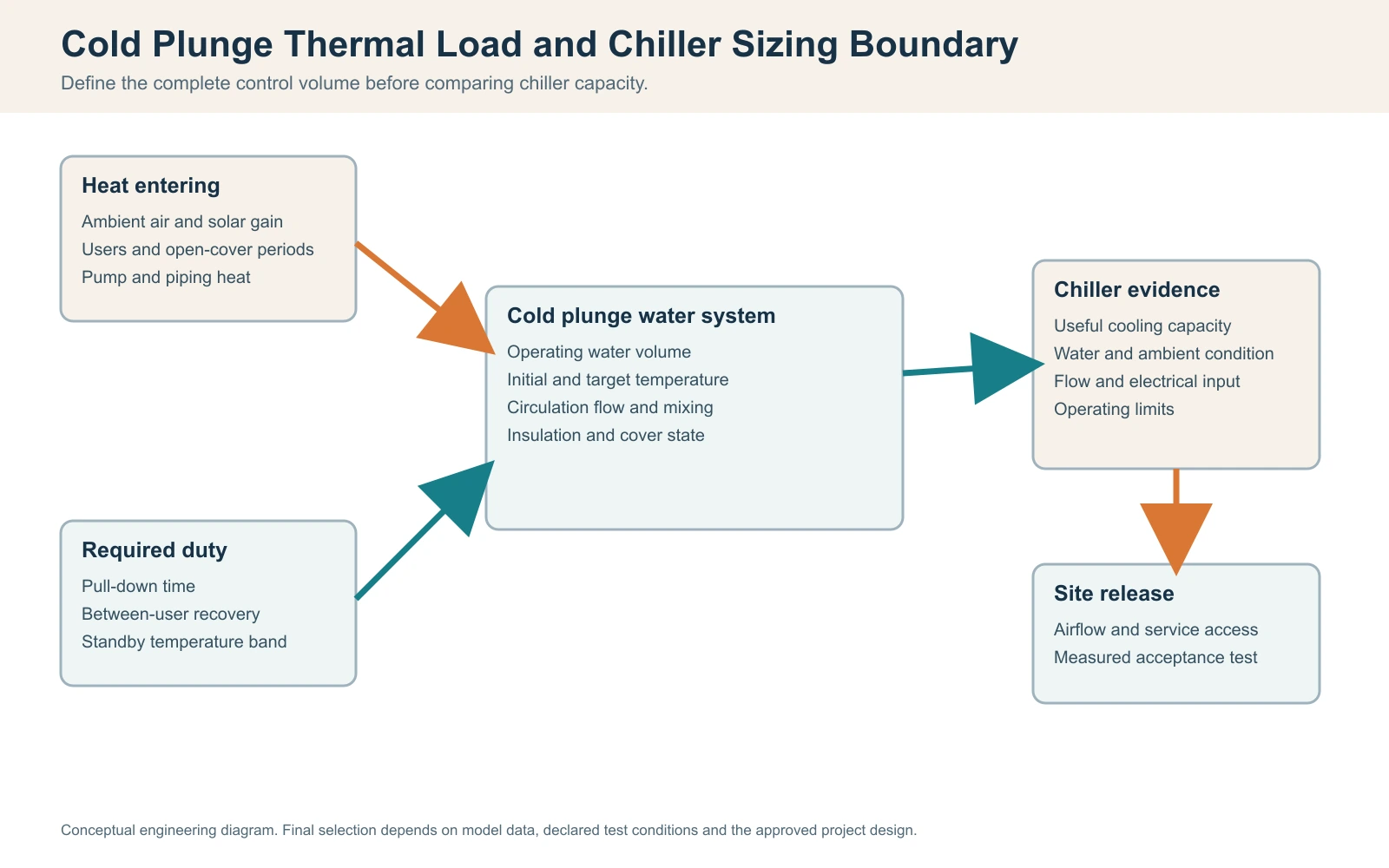
Direct answer: Cold plunge chiller sizing starts with the actual operating water volume, initial and target temperatures, required pull-down and recovery windows, and the heat gains expected during use. Use Q = m x cp x Delta T only to estimate sensible energy in the declared water mass, then compare that duty with useful cooling capacity stated at the relevant water temperature, condenser-intake ambient, flow and filter state, cover and user load, electrical supply, and control condition. Tub volume or compressor horsepower alone cannot establish chiller size. Installed performance still requires a written pull-down, holding and recovery test boundary when the project needs acceptance evidence.
Page scope: This page owns the full thermal-load and chiller-sizing method. Tub-to-chiller interface matching, horsepower-versus-capacity comparison and ambient pull-down diagnosis remain companion topics so those decisions are not duplicated here.
Primary calculation: Q = m x cp x Delta T screens stored water energy; it does not promise field cooling time.
Key comparison: Useful cooling capacity at declared conditions matters more than input horsepower or a maximum label.
Release boundary: Missing volume, flow, ambient, duty, electrical or test evidence keeps the affected sizing or acceptance decision open.
Define the Water Control Volume and Complete Equipment Boundary
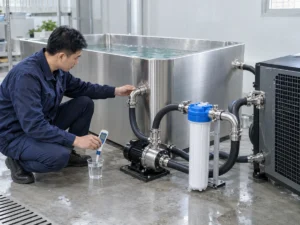
Use two linked boundaries. First, define the water control volume used in the energy calculation: the actual operating water in the vessel plus any included water volume that the calculation intentionally counts. Second, define the complete equipment and site boundary: liner and shell, pipework, filter, pump, heat exchanger, chiller, controls, cover, condenser air and electrical supply. State whether a quoted volume includes hoses, balance tank or filter housing, and do not transfer a related-model or nameplate value into the calculation without confirming its applicability.
Thermal control-volume register
| Element | Required input | Evidence source | Open/hold condition |
|---|---|---|---|
| Water volume | Measured or drawing volume and state | As-built drawing/commissioning | Nominal size only |
| Chiller/heat exchanger | Exact model and configuration | Data sheet/manual | Related model |
| Loop/filter/pump | Pipe, filter, flow and head basis | Hydraulic record | Unverified flow |
| Cover/insulation | Construction and operating policy | Approved specification | Cover assumed |
| Site air/electrical | Intake ambient, voltage, frequency, phase | Final-site and utility data | Generic climate/nameplate |
| Control boundary | Setpoint, sensor, alarm and communications | Released control record | Unfrozen logic |
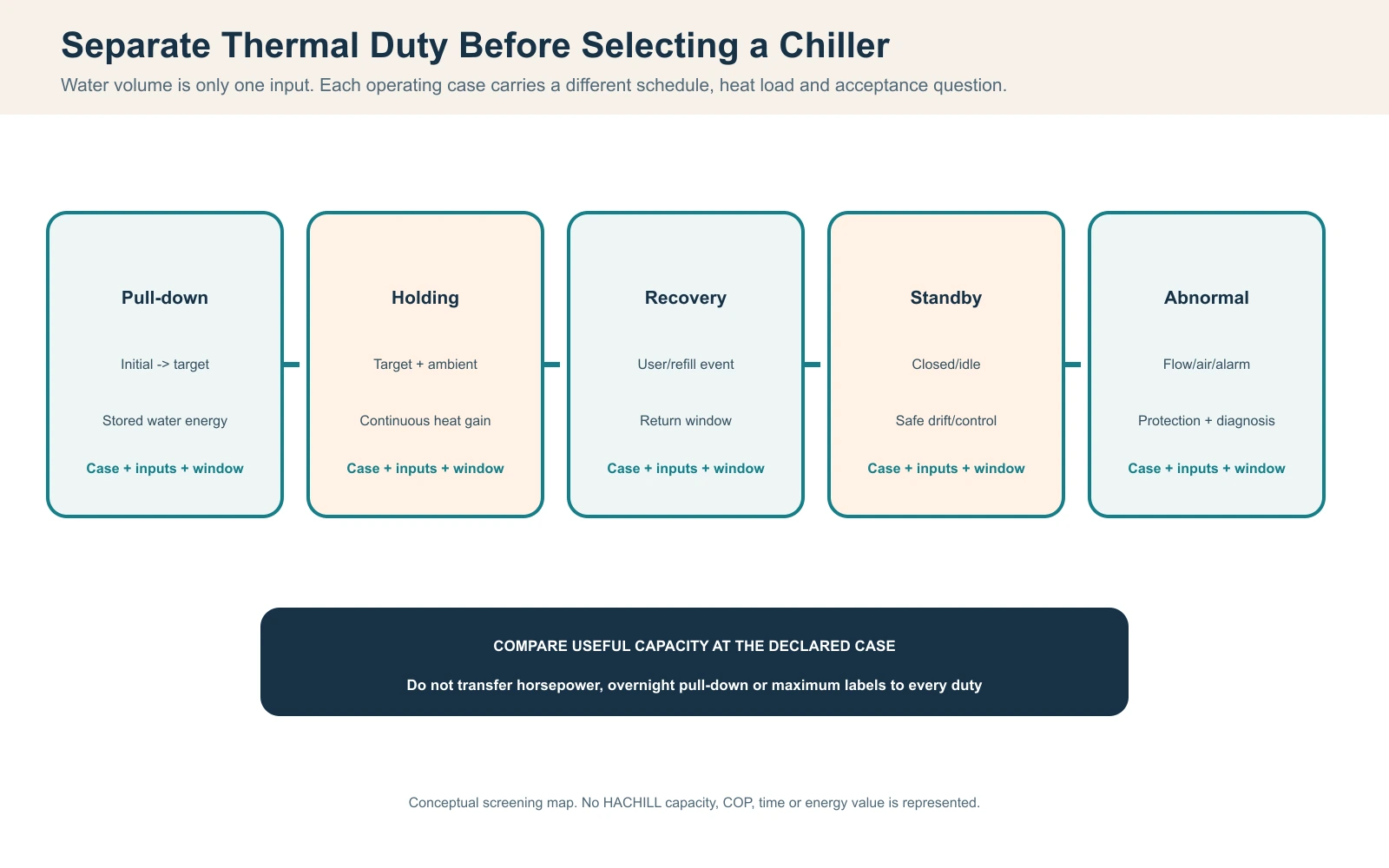
Separate Pull-Down, Holding, Recovery and Standby Duty
One chiller can face different thermal cases. Pull-down removes stored water energy; holding rejects heat entering from ambient, solar, pipework, equipment, cover leakage and users; recovery follows a user event or cleaning/refill; standby may still carry room or plant heat. Define start and target conditions, duration, cover position, user load, allowable drift and the operating schedule for each case.
Cold plunge duty-case register
| Case | Start/operating condition | Required output | Do not infer |
|---|---|---|---|
| Pull-down | Initial water to target, declared ambient | Average rate within window | Rated input power equals cooling |
| Holding | Target water, ambient, cover and site heat | Stable setpoint/allowable drift | Overnight test proves busy use |
| Recovery | User/refill event and schedule | Return within declared window | One event represents all duty |
| Standby | Closed/idle system and plant heat | Safe control and limited drift | No heat gain |
| Abnormal/event | Filter restriction, high air, power or alarm | Protective response and diagnosis | Bypass protection |
Thermal screening sensitivity register
| Variable | Change to test | Expected direction | Evidence boundary |
|---|---|---|---|
| Water volume | Measured vs nominal state | Energy and average rate change | No field result |
| Delta T | Initial/target alternatives | Stored energy changes | Setpoint basis |
| Pull-down window | Required schedule cases | Required average rate changes | No capacity proof |
| Ambient/intake air | Declared hot/cool cases | Useful capacity may change | Site condition |
| Flow/filter state | Approved operating cases | Heat transfer may change | Hydraulic evidence |
| Cover/user load | Closed/open and duty cases | Holding/recovery load changes | Operating policy |
Engineering scenario: the selected horsepower passes overnight but fails the schedule
Observed problem: A vessel reaches target before opening but cannot recover between repeated commercial sessions.
Likely cause: The quote compared input horsepower with a pull-down result and omitted user heat, cover handling, recovery window and intake-air conditions.
How to check: Recreate the schedule with water, ambient, load, cover and control logs; separate average recovery duty from the overnight pull-down case.
Prevention or corrective path: Issue the RFQ with duty cases and acceptance windows. Select or stage equipment using useful capacity at the declared operating point, then test the final schedule.
Calculate Water-Side Energy Without Inventing Performance
For a sensible-water screening calculation, use Q = m x cp x Delta T, where m is the declared water mass, cp is the selected specific-heat basis and Delta T is the declared temperature change. The relationship is shown in the U.S. Department of Energy Thermodynamics, Heat Transfer, and Fluid Flow handbook. If volume is converted to mass, state density and units so the conversion is auditable; NIST SP 811 provides SI unit-use guidance. The result is sensible energy in the declared mass, not a promise that a chiller removes it within the requested time.
For a first-pass average removal rate, divide the declared sensible energy by the required pull-down time, then compare that rate with separately stated heat-gain cases and condition-linked chiller capacity. Do not bury pipe, cover, user, solar, standby or equipment heat inside an unexplained percentage. Record rounding, sensor uncertainty, mixing assumption and whether the water volume is full, normal operating or another declared state. If a calculated loop contains a fluid other than water, use properties for that declared fluid rather than reusing a water basis.
Water-energy calculation record
| Input | Value/source | Unit discipline | Reason |
|---|---|---|---|
| Volume state | Measured/drawing and included components | L, m³ or declared basis | Defines mass |
| Density basis | Declared water condition/source | kg/L or kg/m³ | Converts volume to mass |
| Specific heat | Declared engineering basis | kJ/kg-K or equivalent | Energy factor |
| Initial/target | Measured or required setpoints | °C/°F with conversion | Defines Delta T |
| Pull-down window | Required schedule | s, min or h | Converts energy to rate |
| Other loads | Separate measured/assumed cases | W or kW with source | Prevents hidden allowance |
Illustrative unit-check sequence
| Step | Expression | What it proves | Boundary |
|---|---|---|---|
| Mass | m = rho x V | Volume-to-mass conversion | Density is declared |
| Temperature change | Delta T = Tinitial – Ttarget | Direction and magnitude | Mixed water assumed |
| Stored energy | Q = m x cp x Delta T | Screening energy | No chiller result |
| Average rate | Pavg = Q / t | Required average removal | Heat gains separate |
| Comparison | Useful capacity >= declared case | Offer screening | Exact test condition required |
Match Useful Cooling Capacity to Conditions
Cooling capacity is useful only with the conditions and boundary behind the number. Record water temperature, condenser-intake ambient, flow, inlet condition, control state and electrical basis. Input power, compressor horsepower and cooling capacity are different quantities. AHRI liquid-chiller terminology distinguishes cooling capacity, total power input, COP and rating conditions; use that page as a terminology and rating-condition reference, not as evidence that a particular cold-plunge chiller is AHRI certified or within a specific AHRI standard’s scope.
Compare offers on the same duty case and require each supplier to state what the published capacity and power figures include. If the test boundary or rating condition is missing, keep the value as screening evidence and make the missing condition an RFQ hold item. For a narrower supplier-data comparison, see Cold Plunge Chiller HP vs Cooling Capacity.
Useful-capacity comparison
| Condition | Supplier evidence | Buyer comparison | Hold if |
|---|---|---|---|
| Water inlet/target | Exact test temperature and flow | Same water case | Condition absent |
| Ambient/intake | Measured or declared test air | Same condenser case | Remote weather only |
| Flow/filter | Approved flow and pressure state | Same hydraulic case | Nameplate flow only |
| Control state | Setpoint, cycling and protections | Same duty and controls | Protection bypassed |
| Electrical | Voltage/frequency/phase/current | Target-market match | Utility mismatch |
| Result basis | Net/gross definition and uncertainty | Comparable useful output | Maximum label only |
Engineering scenario: the chiller appears weak after the plant room is enclosed
Observed problem: The same equipment performs during open commissioning but trips or drifts after panels and screens are installed.
Likely cause: Condenser discharge air recirculates and intake air is hotter than the test condition; the rating was transferred without final-site airflow evidence.
How to check: Measure intake and discharge air at the finished enclosure with water, flow, cover and control state; preserve trip records before reset.
Prevention or corrective path: Correct the approved airflow path or revise the equipment case, then repeat the declared hot-condition acceptance test.
Check Flow, Pipe Size, Pressure Loss and Pump Head
Heat transfer depends on water actually moving through the approved circuit. Small pipe, long hose, elbows, valves, a dirty filter, air, wrong pump direction or a restrictive heat exchanger can reduce flow even when the pump runs. Record pipe sizes and lengths, fittings, elevation, filter state, measured or approved proxy flow and the operating control state.
Hydraulic sizing input sheet
| Input | Acquire | Why it matters | Invalid shortcut |
|---|---|---|---|
| Pipe/hose ID and length | As-built measure and drawing | Pressure loss | Nominal connection only |
| Fittings/valves/elevation | Count and schematic | Total head | Straight-pipe assumption |
| Filter state | Condition and service record | Restriction | Clean filter assumption |
| Pump curve/head | Exact model and control speed | Available flow | Pump wattage |
| Heat exchanger requirement | Manual/data point | Transfer duty | Chiller nameplate |
| Air/prime state | Commissioning observation | Avoid dry running/air lock | Pump audible only |
Engineering scenario: a high-capacity chiller cannot hold the target
Observed problem: The selected unit is large on paper, yet the water-side temperature response is poor.
Likely cause: The loop has excessive pressure loss and air, so the heat exchanger receives less flow than the quoted condition.
How to check: Record the approved flow method, filter state, pump/control, air purge and pipe arrangement; compare with the exact test basis.
Prevention or corrective path: Correct the hydraulic cause or select a matched pump/loop within approved limits, then repeat flow and thermal tests together.
Account for Ambient Air, Solar and Condenser Installation
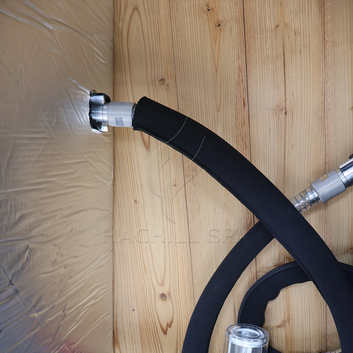
Measure the air where the condenser actually draws it. Walls, roofs, screens, planting and solar load can create a hotter microclimate than a weather app or nearby shade. Check discharge-air recirculation, service clearances, debris, rain protection and whether the accepted cover or enclosure changes heat rejection.
For a focused diagnostic of site-air effects on pull-down, use How Ambient Temperature Changes Cold Plunge Pull-Down Time; this page keeps ambient conditions inside the wider sizing method.
Condenser condition record
| Input | Method | Acceptance use | Invalid state |
|---|---|---|---|
| Intake air | Logger at actual intake | Condition-linked capacity | Distant city data |
| Discharge air path | Final-site observation | Recirculation check | Open test arrangement |
| Solar/roof/screen | Timestamped site record | Concurrent heat gain | Shade differs |
| Debris/coil access | Inspection and service trial | Sustained airflow | Access assumed |
| Rain/condensation | Wet-state observation | Equipment protection | Weather claim |
| Electrical/control | Qualified record and alarm state | Protection behavior | Bypass/reset only |
Include Insulation, Cover, Pipe and User Heat Gains
Holding duty is often governed by gains after pull-down. Record insulation construction and continuity, cover fit and handling, exposed pipe runs, equipment heat, room or outdoor air, solar, cleaning/refill and user entry. A cover can reduce heat gain but also changes condenser access and operating practice. Do not turn a visual cover claim into a quantified saving without a declared test.
Heat-gain register
| Source | Acquire | Effect on duty | Evidence boundary |
|---|---|---|---|
| Tub wall/base | Construction and thermal path | Standby/holding gain | No generic R-value |
| Cover/opening | Fit, policy and event log | Surface/user heat gain | Closed-only test |
| Pipe/equipment | Length, exposure and insulation | Continuous gain | Hidden route assumption |
| Users/refill/cleaning | Count, water state and schedule | Recovery load | Overnight proxy |
| Solar/room air | Final-site conditions | Ambient gain | Regional average |
| Thermal bridge/leak | Inspection and trend | Unexpected gain | Cause unknown |
Freeze Electrical and Control Interfaces Before Ordering
Voltage, frequency, phase, rated current, startup behavior, protection, disconnect, grounding, communication, sensor location and control ownership must be established for the exact ordered equipment and destination. A cooling selection can be thermally suitable but unusable if the supply or protection does not match. Final conductor sizing, overcurrent protection, disconnects, grounding and field wiring must follow the equipment documentation and applicable local electrical requirements, with regulated work performed by qualified local professionals.
Electrical and control interface schedule
| Interface | Required input | Evidence | Hold condition |
|---|---|---|---|
| Voltage/frequency/phase | Target market utility | Nameplate and approved submittal | Mismatch or late change |
| Current/startup/protection | Qualified electrical basis | Design/test record | Protection assumed |
| Disconnect/grounding | Final location and responsibility | Qualified installation | Access/ground open |
| Sensors/setpoints | Location, range and control owner | Control record | Sensor basis unknown |
| Alarms/interlocks | Flow, temperature, pressure and outage logic | Functional test | Protection bypass |
| Communication/data | Protocol and handover | Approved integration record | Unowned interface |
Create a Defensible Condition-Linked Cooling Test
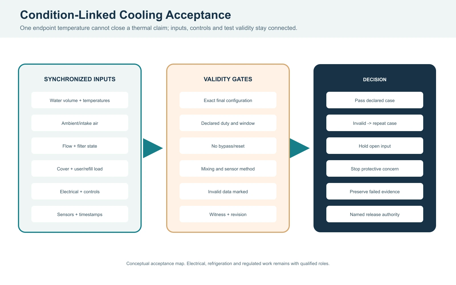
Before testing, declare the exact equipment, water volume, initial and target temperatures, ambient/intake air, flow and filter state, cover, user or refill load, electrical supply, controls, duration, data interval, stop conditions and acceptance window. Synchronize water, air, flow, control and alarm data. A single endpoint temperature cannot explain a thermal result.
Separate pull-down, holding and recovery tests. Mark data invalid if the final enclosure is changed, sensors move, water is not mixed, flow is outside the declared case, protection is bypassed or required inputs are missing. Preserve failed tests and repeat only after the cause is addressed.
Cold plunge cooling acceptance record
| Gate | Required record | Pass boundary | Stop/invalid condition |
|---|---|---|---|
| Documents | Exact model, limits, configuration and roles | All inputs frozen | Related-model evidence |
| Pull-down | Water/air/flow/control time series | Declared window and condition | Missing volume or sensor |
| Holding | Target, cover, ambient and drift trend | Declared allowable drift | Different cover/load |
| Recovery | User/refill case and restart state | Declared schedule | Overnight proxy |
| Protection | Alarm/interlock and qualified response | Functions operate as designed | Bypass/reset |
| Release | Cause, correction, retest and authority | Documented condition-specific release by the named authority | Open dependent check |
Engineering scenario: a fair-weather test is used to close a commercial acceptance
Observed problem: The unit passes in cool shade but no recovery or high-ambient test exists for the operating schedule.
Likely cause: The team treated one test endpoint as proof of every duty case and did not preserve the missing condition as an open item.
How to check: Compare the signed test plan with actual water, ambient, flow, cover, load and schedule; identify untested cases and invalid assumptions.
Prevention or corrective path: Keep the unsupported case open and run condition-specific pull-down, holding and recovery tests before release.
Grade Thermal Evidence and Assign Responsibilities
Project thermal evidence ladder — an editorial decision framework for this page, not an industry standard or certification grade.
| Grade | Evidence | Permitted use | Boundary |
|---|---|---|---|
| A | Witnessed exact-system test at declared condition | Condition-specific acceptance | Declared duration/method |
| B | Approved exact-model data point/manual | Sizing/submittal basis | Field condition separate |
| C | Component or calculation record | Screening/interface support | Complete performance unproven |
| D | Qualified estimate with assumptions | Planning/open item | Cannot close release |
| E | Horsepower label or generic claim | Orientation | No useful-capacity proof |
Thermal responsibility matrix
| Decision | Supplier | Buyer/project | Qualified/local role |
|---|---|---|---|
| Model/capacity evidence | Provide exact test basis | Compare and freeze inputs | Review project case |
| Volume/thermal case | State assumptions | Supply measured/site data | Approve design basis |
| Hydraulic/air interfaces | State limits | Coordinate final site | Design/install/verify |
| Electrical/control | Supply interface data | Freeze target market | Qualified design/test |
| Acceptance/retest | Provide affected inputs | Witness/preserve records | Authorize regulated work/release |
HACHILL Product Engineering can review supplied-product inputs and an RFQ. It cannot replace the qualified local authority responsible for electrical, structural, refrigeration, public-health or building work.
Use Hold Points, Dispute Records and Controlled Retest
Hold release when a volume state, useful-capacity condition, flow, intake air, electrical interface, control protection, sensor location or duty case is unknown. Preserve test timestamps, instruments, configuration revision, water and air conditions, filter/flow state, cover/load, control state, photographs and witness identity. Identify cause before changing multiple variables.
Thermal dispute and retest record
| Issue | Evidence to preserve | Correction | Dependent retest |
|---|---|---|---|
| Capacity disagreement | Condition, units, data and test basis | Normalize inputs | Same duty case |
| Flow restriction | Pipe/filter/pump/air state | Correct hydraulic cause | Flow + thermal |
| High ambient trip | Intake/discharge and control log | Correct airflow/site | Hot-condition test |
| Electrical mismatch | Utility/protection/control state | Qualified correction | Protection + operation |
| Sensor/data dispute | Location/calibration/time series | Reposition/verify | Repeat affected case |
| Failed acceptance | Original report and witness | Cause/disposition | All affected gates |
Engineering scenario: a valid calculation is rejected because the field record is incomplete
Observed problem: The procurement team calculates a plausible average cooling rate, but the supplier and installer reach different conclusions during commissioning. The calculation lists the vessel volume and temperature change, while the site record omits the actual water level, mixing state, filter pressure, intake-air temperature, cover position, and control mode.
Likely cause: The parties are comparing different system boundaries and different duty cases. One result represents stored water energy under an assumed full volume; the other reflects a restricted loop, an open cover, and a warmer equipment enclosure. Neither result can be reconciled from a final water-temperature endpoint alone.
How to check: Freeze one test sheet with the exact model and configuration, instrument locations, time zone, sampling interval, water volume state, initial and target temperatures, intake and discharge air, flow or approved hydraulic proxy, filter condition, cover/load event, voltage/frequency/phase, setpoint, alarms, and witness names. Record the same fields at the start, during the run, and at release. Keep raw readings, photographs, calibration status and the calculation revision together.
Prevention or corrective path: Classify the calculation as a screening record until an exact-condition test is witnessed. If the field result differs, first normalize units and boundary conditions, then isolate one cause at a time: restore flow, correct airflow, stabilize the water mix, or repeat the declared duty case. Do not change the chiller, pump and controls simultaneously because that removes the evidence needed to assign responsibility. A release decision should identify the tested case, untested cases, open risks and the authority who accepts the limitation.
Evidence rule: Keep the original failed record in the project file. A corrected retest is evidence for the corrected condition, not proof that the earlier condition passed. Record who accepted the boundary, which cases remain untested, and which dependent checks must be repeated before release.
Issue a Normalized Chiller-Sizing RFQ
Send water volume and included components, initial and target temperatures, pull-down/holding/recovery schedule, ambient and condenser location, cover and insulation, user/refill load, pipe and filter arrangement, flow/head, voltage/frequency/phase, target market, indoor/outdoor condition, quantity, controls, certification target and acceptance witness. Ask each supplier to mark tested, calculated, estimated and open values.
Cold plunge chiller sizing RFQ fields
| Field | Why required | Supplier response | Closure |
|---|---|---|---|
| Exact volume/configuration | Sets control volume | Model, BOM and assumptions | Technical bid |
| Duty cases | Sets useful output | Pull-down/holding/recovery basis | Test plan |
| Ambient/airflow | Sets condenser condition | Limits and site arrangement | Installation |
| Hydraulic/flow | Sets heat-transfer condition | Pipe/filter/pump inputs | Commissioning |
| Electrical/control | Sets target-market fit | Voltage, protection, sensors | Qualified review |
| Evidence/acceptance | Makes offers comparable | Data, witness and retest | Release gate |
Frequently Asked Questions
How do I size a chiller for a cold plunge?
Start with water volume, initial and target temperature, required pull-down window, holding/recovery duty, ambient, insulation, cover, user load, flow and electrical conditions. Use Q = m x cp x Delta T as a screening calculation, then compare useful capacity at declared conditions.
Is chiller horsepower the same as cooling capacity?
No. Input power or compressor horsepower is not delivered cooling capacity. Request a condition-linked capacity basis that states water temperature, ambient, flow, controls and whether the value is gross or net.
Why can a large chiller still cool poorly?
Low flow, a restricted filter, air in the loop, undersized pipe, condenser-air recirculation, high ambient, cover/load or control protection can limit heat transfer. Synchronize hydraulic, air, water and control data before changing equipment.
What should a commercial cooling acceptance test include?
Declare the exact configuration, water and duty case, ambient/intake air, flow/filter state, cover/load, electrical supply, controls, duration, sensors, stop conditions and acceptance window. Separate pull-down, holding and recovery tests.
Can a pull-down calculation guarantee cooling time?
No. Q = m x cp x Delta T estimates stored water energy. Actual time depends on useful capacity at the operating condition and on heat gains, flow, controls, ambient and measurement method.
Reference Basis and Limits
U.S. Department of Energy Thermodynamics, Heat Transfer, and Fluid Flow supports the sensible-heat relationship used for screening; it does not provide an HACHILL cold-plunge rating or field-performance guarantee.
NIST SP 811, Guide for the Use of the International System of Units (SI) supports consistent unit notation and conversion discipline; it does not validate project inputs.
AHRI liquid-chiller terminology supports the distinction between cooling capacity, total power input, COP and rating conditions. It is cited here for terminology; no AHRI certification or standard-scope claim is made for a HACHILL chiller.
Technical boundary: No exact HACHILL cooling capacity, COP, pull-down time, energy cost, noise, flow, temperature limit, warranty or certification is claimed here. Exact product data, test conditions, manuals and qualified local requirements control.
Turn thermal inputs into a matched chiller brief
Send HACHILL the exact water volume, initial and target temperatures, duty cases, ambient and condenser location, cover and insulation, user load, flow and filter state, voltage/frequency/phase, target market, quantity and acceptance needs. The team can review supplied-product inputs while qualified local parties retain design authority.