COLD PLUNGE ENGINEERING GUIDE
Engineering guidance for cold plunge chiller HP vs cooling capacity, focused on the selection inputs, evidence and project checks needed before procurement or site release.
Engineering Decision Guide
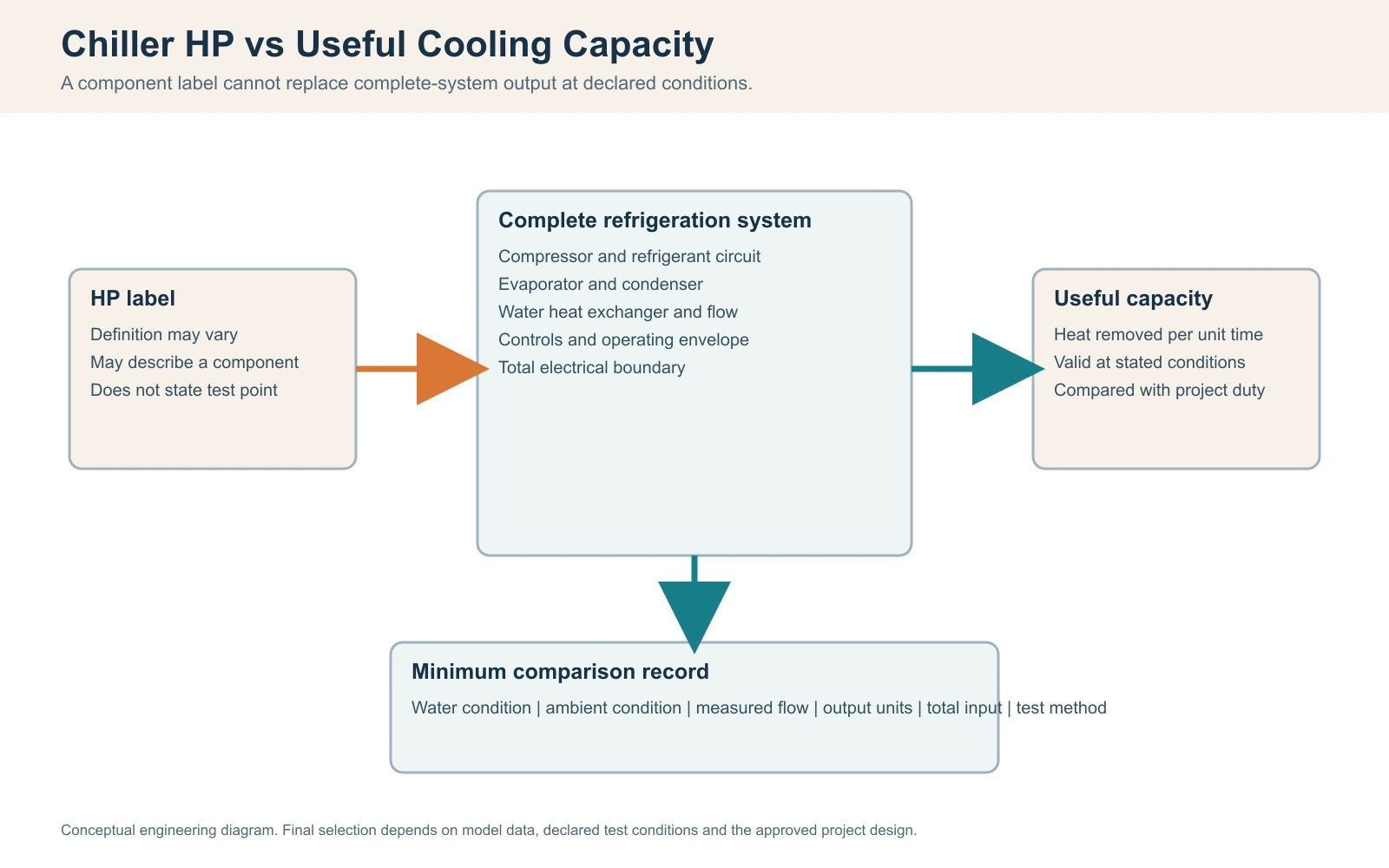
Direct answer: Horsepower does not tell a cold-plunge buyer how much heat the complete system will remove at the project’s water temperature, ambient condition and flow. HP may identify a compressor or motor class; useful cooling capacity is an output rate, normally stated in kW or BTU/h, at declared test conditions. Input power and COP answer different questions again.
A defensible comparison starts with operating water volume, start and target temperatures, pull-down time, holding load, users per hour, condenser-intake temperature, water flow and total electrical boundary. Calculate the duty, request capacity at matching conditions, and define how the result will be measured before purchase-order release. Without that chain, two quotations can show the same HP while describing different equipment, or show the same cooling capacity while using conditions that cannot be compared.

HP and Cooling Capacity Answer Different Buyer Questions
A supplier data sheet may place HP, cooling capacity, input power and COP in one specification table. Their proximity does not make them interchangeable.
Horsepower is a descriptor, not delivered cooling
Mechanical horsepower is a unit of power, and one mechanical horsepower is approximately 746 watts. That conversion does not mean a 1 HP compressor produces 0.746 kW of cooling. Refrigeration equipment moves heat through a vapor-compression cycle. The useful cooling output depends on compressor design, refrigerant circuit, evaporator and condenser heat exchangers, fan performance, controls, water flow, water temperature and condenser-intake condition.
The buyer must therefore ask what the HP field names. It may refer to a compressor motor class, a nominal compressor designation, a pump motor, or a product-series label. If the supplier cannot define it, retain HP only as an identification field. Do not use it as the contractual output.
Cooling capacity is useful output at a stated condition
Cooling capacity is the rate at which the defined system removes heat. It may be reported as watts, kilowatts, BTU/h or refrigeration tons. Unit conversion is straightforward: 1 kW is approximately 3,412 BTU/h. Comparability is not straightforward. A 2.5 kW figure at warm entering water and moderate ambient air may not remain 2.5 kW as water approaches a low cold-plunge setpoint or as condenser intake rises.
The value is incomplete unless the record identifies at least:
- water temperature or entering/leaving water conditions;
- condenser-intake ambient temperature;
- water flow through the heat exchanger;
- electrical supply and control state;
- whether the pump, fan and auxiliaries are inside the test boundary;
- whether capacity is measured, calculated, simulated or nominal.
Input power describes demand, not output
Total electrical input is needed for site coordination and efficiency comparison. A compressor-only input and a complete-system input are different boundaries. If one quotation includes condenser fan, circulation pump and controls while another lists compressor input only, their input figures and COP values cannot be compared directly.
Nameplate maximum current also does not equal average operating power. It supports electrical protection and conductor selection by a qualified professional, but it does not by itself predict energy use over a changing pull-down or holding cycle.
COP compares output with input only inside the same boundary
For cooling, a simplified coefficient of performance is:
COP = useful cooling output / electrical input
If useful output is 2.4 kW and complete measured input is 1.0 kW at the same stable condition, the calculated COP is 2.4. If the 1.0 kW excludes a 0.2 kW pump that the other supplier includes, the comparison is biased. A single COP point also does not describe performance across a complete pull-down, low-water-temperature operation or hot-ambient condition.
| Field | Buyer question it can answer | What it cannot prove alone | Required qualifier |
|---|---|---|---|
| HP | Which component or product class is declared? | Delivered cooling, cooling time or efficiency | Definition of the HP field |
| Cooling capacity | How quickly is heat removed at one condition? | Output at every water and ambient condition | Water, ambient, flow and test boundary |
| Total input | What electrical demand occurred at the test point? | Annual use or useful output | Included components and supply condition |
| COP | What was the output/input relationship at one boundary? | Part-load or seasonal performance | Same output and input boundary |
| Setpoint | What temperature can the control request? | Ability to reach or hold it at project duty | Load, capacity, flow and operating limits |

Define Three Duties Before Comparing a Chiller
The project does not have one cooling requirement. It has at least three. A unit can pass one and fail another.
Pull-down duty
Pull-down is the planned reduction from an initial water temperature to a target temperature within an agreed time. The basis must identify actual operating water volume, not only the vessel's external dimensions or gross fill volume. It must also state whether the cover is on, whether the system starts after a fresh fill, and the design ambient condition.
Pull-down is often a commissioning or start-of-day requirement. A commercial venue that fills or warms the vessel between operating periods may care about it strongly. Another venue that holds temperature continuously may be governed instead by recovery and holding duty.
Holding duty
Holding duty is the heat that enters while the system maintains a temperature band. Sources can include the open water surface, vessel and pipe heat gain, solar exposure, warm air, pump heat, nearby equipment and repeated cover removal. The load changes through the day. A covered overnight test is not evidence for an uncovered afternoon operation unless the buyer accepts that boundary.
Holding also depends on control behavior. The system may cycle inside a setpoint band instead of producing constant output. Record the controller's measured variable, sensor location, start/stop logic and any minimum run or anti-short-cycle behavior that materially affects the test.
Post-use recovery duty
Recovery is the system's ability to return to an agreed temperature band after user sessions or another defined heat event. "Users per day" is too weak for this decision. Ten users spread across ten hours create a different recovery problem from ten users in one hour.
Define the session block, number of entries, approximate exposure pattern where operationally relevant, cover state, mixing period and required recovery endpoint. Do not convert a user's body heat into a universal load assumption. Where project data are unavailable, measure the bulk-water temperature rise during a representative, controlled operating period and retain the record as a project input.
| Duty | Required inputs | Acceptance output | Common specification error |
|---|---|---|---|
| Pull-down | Operating volume, start/target temperature, time, ambient, cover, flow | Time-temperature curve and endpoint | Selecting from tub volume alone |
| Holding | Temperature band, schedule, ambient, solar, cover, insulation, pump heat | Stable band and cycling record | Using a covered night test for daytime duty |
| Recovery | Session pattern, measured temperature rise, required return time | Recovery curve to stated band | Using users/day instead of users/hour |
Before a supplier recommendation, the buyer should complete a duty-basis record.
| Input | Value and unit | Evidence source | Owner | Open if unknown |
|---|---|---|---|---|
| Operating water volume | Approved fill calculation or measured fill | Buyer / supplier | Yes | |
| Initial and target temperature | Operating brief | Buyer / operator | Yes | |
| Required pull-down time | Operating schedule | Buyer / operator | Yes | |
| Peak condenser-intake ambient | Site design or measurement | Site team | Yes | |
| Cover and solar state | Operating and site plan | Buyer / designer | Yes | |
| Users per session block | Booking/throughput plan | Operator | Yes | |
| Required recovery band and time | Operating brief | Operator | Yes | |
| Water flow and circuit resistance | Hydraulic calculation/test | Installer / supplier | Yes | |
| Electrical supply | Site electrical schedule | Qualified local professional | Yes |
Calculate the Water Load, Then Expose the Assumptions
A transparent calculation is not a promise of performance. Its purpose is to show which inputs control the decision and to reveal where supplier data must replace an assumption.
Step 1: calculate the thermal energy removed from the water
For a first-pass calculation using water without a significant additive concentration:
Q = m x cp x Delta T
where:
Qis thermal energy, in kJ;mis water mass, in kg;cpis the assumed specific heat capacity, in kJ/(kg K);Delta Tis the water temperature reduction, in K or degrees C.
For early screening, water mass in kilograms is often approximated from volume in liters using approximately 1 kg/L, and cp is often approximated as 4.186 kJ/(kg K) near the relevant liquid-water range. The final calculation should use an appropriate property basis if additives, unusual temperatures or higher precision matter.
Illustrative input set:
- operating volume: 300 L, approximated as 300 kg;
- initial temperature: 25 C;
- target temperature: 10 C;
- temperature reduction: 15 K.
The water-only energy is:
Q = 300 kg x 4.186 kJ/(kg K) x 15 K = 18,837 kJ
To convert kJ to kWh, divide by 3,600:
18,837 kJ / 3,600 = 5.23 kWh of thermal energy
This is not the electrical energy use. It is the heat that must be removed from the water under the stated approximation. It excludes heat entering during the test and thermal energy in the vessel, pipework and connected components.
Step 2: separate gross chiller capacity from net capacity available to the water
If a condition-linked chiller output averages 2.4 kW during the relevant part of the pull-down and ongoing heat entering the defined water system averages 0.4 kW, the simplified net capacity is:
Net capacity = 2.4 kW - 0.4 kW = 2.0 kW
The idealized time based on the water-only energy is:
Time = 5.23 kWh / 2.0 kW = 2.62 hours
That result is an illustration, not a forecast for a product. The 2.4 kW output and 0.4 kW heat-gain assumptions must be replaced with condition-linked data or a measured curve. If chiller capacity falls as water temperature falls, using one average value without a performance map can understate the elapsed time.
Step 3: treat capacity as a curve when conditions change
During pull-down, water temperature changes continuously. Ambient air and solar exposure may also change. A stronger model divides the pull-down into intervals and uses capacity appropriate to each interval:
Delta time_i = thermal energy removed in interval_i / net capacity_i
The total time is the sum of all intervals. A measured time-series test can be more reliable than an elaborate calculation when the exact configuration exists, provided the test boundary matches the project and the instruments and data treatment are controlled.
Step 4: quantify recovery from a measured bulk-water rise
Assume the same illustrative 300 L system rises by 1.2 K during a defined session block after the water is mixed and the measurement is stable. The added water energy is approximately:
Q_recovery = 300 kg x 4.186 kJ/(kg K) x 1.2 K = 1,507 kJ
1,507 kJ / 3,600 = 0.419 kWh thermal
At an illustrative net recovery capacity of 2.0 kW, the water-only ideal recovery time is:
0.419 kWh / 2.0 kW = 0.210 hours, or about 12.6 minutes
Actual recovery can be longer because the capacity and heat gain vary, the controller may cycle, and the temperature reading may not represent fully mixed water. The value is useful only when the session definition, measurement point and endpoint are recorded.
| Calculation item | Illustrative value | Source type | Sensitivity / limitation |
|---|---|---|---|
| Operating volume | 300 L | Assumption | Must be replaced by measured or approved volume |
| Water mass approximation | 300 kg | Engineering approximation | Changes with fluid composition and temperature |
| Initial / target | 25 C / 10 C | Assumption | Project operating requirement controls |
| Specific heat | 4.186 kJ/(kg K) | Engineering approximation | Use appropriate fluid properties where precision matters |
| Water-only energy | 5.23 kWh thermal | Calculated | Excludes vessel and ongoing heat gains |
| Gross average output | 2.4 kW | Assumption | Must be condition-linked, not inferred from HP |
| Ongoing heat gain | 0.4 kW | Assumption | Site, cover, solar, pipework and pump change it |
| Net average output | 2.0 kW | Calculated assumption | Varies through pull-down |
| Idealized time | 2.62 h | Calculated illustration | Not a product or site guarantee |
For the full equipment-selection model, continue to the cold plunge thermal engineering and chiller sizing guide.
Measure Useful Water-Side Capacity Instead of Inferring It from HP
Two measurement routes are practical for procurement and commissioning: a steady water-side heat-balance test and a complete-system pull-down test. They answer related but different questions.
Steady water-side method
Where stable flow and a measurable chiller inlet-to-outlet temperature difference are available, useful water-side capacity can be estimated by:
Cooling rate = mass flow x cp x (T_in - T_out)
For an illustrative pure-water approximation:
- measured flow: 30 L/min, approximately 0.50 kg/s;
- chiller inlet-to-outlet temperature difference: 1.0 K;
- assumed
cp: 4.186 kJ/(kg K).
Then:
Cooling rate = 0.50 kg/s x 4.186 kJ/(kg K) x 1.0 K = 2.09 kW
This method can fail quietly when the temperature difference is small. If two sensors each have material error relative to a 1.0 K difference, the calculated capacity can shift substantially. Use paired or characterized sensors, consistent immersion and placement, stable flow, synchronized timestamps and an uncertainty review appropriate to the decision. A display that shows temperatures to 0.1 C does not prove 0.1 C accuracy.
Mass flow should be measured or defensibly derived at the actual operating point. A pump label or unrestricted nominal flow does not establish flow through a circuit containing hoses, elbows, valves, filters and a heat exchanger.
Complete-system pull-down method
A pull-down test measures the result of the installed system, including control behavior and ongoing site loads. Record:
- verified operating water volume;
- water temperature at a representative mixed location;
- chiller inlet and outlet temperatures where available;
- condenser-intake air temperature, not only room or weather data;
- water flow or a validated flow indicator;
- total electrical input where efficiency is being evaluated;
- cover, solar and door/enclosure state;
- filter condition and clean commissioning baseline;
- start time, endpoint and data exclusions;
- controller setpoint, mode and alarm history.
Use a sampling interval short enough to show cycling and changing slope. State the interval in the protocol rather than applying one universal interval to every instrument and controller.
Mixing and sensor location control the meaning of the result
A sensor near the cold return can report a lower temperature than the bulk vessel. A sensor near a warm surface or user zone can report higher. Agree whether the acceptance endpoint is a mixed bulk-water temperature, a controller reading or another defined measurement. For a mixed endpoint, document how circulation and any manual mixing are controlled before the reading is accepted.
Data traceability must match the decision risk
NIST describes metrological traceability as a documented unbroken chain of calibrations, each contributing to measurement uncertainty. A field acceptance test does not automatically require a national laboratory to be present, but the buyer should know instrument identity, calibration or verification status, range, resolution, placement and time synchronization. The required rigor should scale with contract value and dispute risk.
| Timestamp | Bulk water | Chiller inlet | Chiller outlet | Condenser intake | Flow | Total input | Cover / solar | Control state / alarm | Note |
|---|---|---|---|---|---|---|---|---|---|
| Test start | |||||||||
| Interval record | |||||||||
| Control transition | |||||||||
| Test endpoint |
Data-quality hold: Do not use the result to reject or approve equipment when operating volume, temperature location, flow status or condenser-intake condition is unknown. Close the data gap or repeat the test under a controlled boundary.

Normalize Supplier Quotations into One Evidence Record
The buyer's comparison sheet should preserve what each supplier actually stated. Do not silently convert unmatched data into an apparently uniform table.
Required capacity fields
For every capacity point, request:
- useful cooling output and unit;
- water entering/leaving or operating temperature;
- condenser-intake air condition;
- measured or required water flow;
- electrical supply;
- total-input boundary;
- control state and test duration or stabilization rule;
- source: measured, calculated, simulated or nominal;
- model and configuration revision;
- applicable operating limits and protection conditions.
If a supplier provides only HP and a maximum tub volume, mark cooling capacity as not evidenced. If a supplier provides capacity without test conditions, mark the conditions as open. Neither omission proves poor equipment, but neither supports a condition-specific project decision.
Convert units, not conditions
BTU/h can be converted to kW and vice versa. Fahrenheit temperature differences can be converted to Kelvin or Celsius differences. Those conversions do not normalize different entering-water temperatures, ambient conditions, flow or included auxiliaries.
When conditions differ, use one of three routes:
- request capacity at the buyer's common comparison point;
- use a supplier performance map or approved interpolation method;
- retain the data as unmatched and make the uncertainty visible.
Do not create a derating factor without a technical basis.
Define the COP boundary
Request both useful output and total input at the same condition. List compressor, fan, pump, controls and any heater separately where possible, then state which are included in the COP. If a pump is site-supplied, the product COP and installed-system COP are different decisions.
| Supplier field | Mandatory statement | Evidence source | Hold / reject condition |
|---|---|---|---|
| HP | Component or designation represented | Model-specific data sheet | Undefined HP cannot be used for ranking |
| Cooling output | kW or BTU/h | Condition-linked record | No conditions or source stated |
| Water condition | Entering/leaving or operating point | Test record / performance map | Different points treated as equivalent |
| Ambient | Condenser-intake condition | Test record / map | Room average substituted for equipment intake |
| Flow | Required and test flow | Flow record / approved range | Nominal pump label only |
| Total input | Included components and supply | Metered record / data sheet | Compressor-only value presented as system input |
| COP | Output and input boundary | Calculation with source fields | Boundaries or conditions do not match |
| Controls | Setpoint, mode and cycling state | Test protocol | Unstable or undisclosed mode |
| Configuration | Model, revision and options | Controlled submittal | Evidence belongs to another configuration |
Before requesting a model recommendation, assemble the operating volume, temperatures, time, ambient, flow and electrical data. A supplier can then respond to a defined duty instead of guessing from HP.
Grade Evidence Before Relying on a Performance Claim
Evidence quality has two dimensions: strength and scope. A strong record for one model at one condition does not automatically apply to every model or site.
| Level | Evidence | Suitable use | Does not automatically prove |
|---|---|---|---|
| 1 | Order-specific witnessed test at agreed project condition, with controlled instruments and configuration | Final acceptance for the stated order and boundary | Performance outside that condition or after site changes |
| 2 | Model-specific independent or accredited-laboratory report at matched conditions | High-confidence model comparison within report scope | HACHILL certification, every option, installed-site result |
| 3 | Model-specific manufacturer test or performance map with conditions, method and revision | Selection and technical submittal when accepted by buyer | Independent verification or unmatched site performance |
| 4 | Engineering calculation with disclosed inputs and assumptions | Screening, gap identification and test planning | Measured product performance |
| 5 | Generic brochure, HP label, unsourced volume chart or verbal claim | Lead identification only | Capacity, cooling time, efficiency or project acceptance |
Evidence must match the ordered configuration. A capacity report for a different heat exchanger, compressor, pump, power supply or control revision should be treated as a gap until the supplier explains applicability in writing.
An official standard can define a rating method or equipment scope; it does not prove that a product has been tested or certified to that standard. AHRI maintains performance-rating standards intended to make equipment specifications and evaluations more consistent. The applicable standard, its scope and any related certification must be verified for the exact cold-plunge chiller model and destination market. A standards-directory reference must never be used as decoration or implied certification.
Account for Site, Hydraulic and Control Losses
A valid factory rating can coexist with weak field performance. The next task is to determine whether the field boundary matches the rating boundary.
Air-side conditions
An air-cooled condenser must reject the heat removed from the water plus compressor work. High intake air, blocked coil area or discharge recirculation can reduce available capacity or trigger protection. Measure air where the condenser takes it in. A room thermostat several meters away may not capture the microclimate inside a cabinet or behind a screen.
Typical installation planning example
- Problem: A chiller with condition-linked capacity data misses the pull-down endpoint after decorative screening is installed.
- Likely cause: Hot condenser discharge air returns to the intake, so the equipment operates above the specified ambient condition.
- Evidence check: Log condenser-intake and discharge temperature, inspect airflow direction and compare clearances with the approved installation instructions.
- Prevention/decision: Restore the approved air path and repeat the controlled test before changing capacity or rejecting the unit.
Water-side conditions
The heat exchanger needs flow within its approved range. Pipe diameter, total length, elbows, valves, filter loading, elevation effects where applicable and air in the circuit change the operating point. More pump nameplate flow does not guarantee more circuit flow, and more flow is not always better if it exceeds component limits.
Establish a clean-filter commissioning baseline. Later performance can then be compared with pressure, flow or other approved indicators. If the filter is blocked or the circuit contains air, restore the hydraulic condition before interpreting a refrigeration-capacity shortfall.
Controls and electrical boundary
Controller sensor position, deadband, anti-short-cycle logic, minimum run time and alarms affect the observed curve. Voltage and frequency must match the equipment and destination. Fixed electrical work, protective devices, grounding, bonding and local code compliance require a qualified local professional. A performance test must not bypass a safety control to force continuous operation.

Use the dedicated guides to evaluate ambient-temperature effects on pull-down and duty-cycle and oversizing trade-offs.
Assign Responsibility and Hold Points Before Purchase-Order Release
Performance disputes often begin as ownership gaps. The supplier assumes the site will provide flow and airflow; the installer assumes the equipment selection already accounts for the circuit; the buyer assumes the headline capacity covers the operating schedule. A responsibility matrix makes those assumptions visible.
| Decision / record | Supplier / manufacturer | Buyer / operator | Installer / site team | Qualified local professional / authority | Commissioning witness |
|---|---|---|---|---|---|
| Duty basis | Consulted; reviews | Responsible; approves | Provides site inputs | Reviews regulated interfaces | Informed |
| Model performance map | Responsible; provides evidence | Reviews / approves basis | Consulted | Informed where required | Reviews test point |
| Hydraulic route and actual flow | Provides limits and supplied-component data | Approves operating need | Responsible for design/installation/measurement | Reviews where required | Verifies record |
| Condenser airflow | Provides required envelope | Protects lifecycle access | Responsible for installed path | Reviews building interface where required | Verifies condition |
| Electrical supply and protection | Provides equipment requirements | Provides destination and site brief | Coordinates installation | Responsible for local design/approval | Verifies documentation, not design authority |
| Acceptance protocol | Provides test method input | Responsible for commercial acceptance | Provides site readiness | Consulted for regulated scope | Witnesses / records if appointed |
| Deviation closure | Explains product-side deviation | Approves disposition | Closes installation deviations | Approves regulated changes where required | Confirms retest record |
Use four hold points:
- Design-input hold: operating volume, temperature duty, ambient, use schedule, utilities and responsibility are approved.
- Technical-submittal hold: model-specific capacity, flow, input boundary, controls, drawings and evidence scope are accepted.
- Shipment hold: ordered configuration, revision, labels, manuals, test records and packing scope match the approved submittal.
- Commissioning hold: installation, flow, airflow, electrical records, sensor setup and acceptance protocol are ready before performance is judged.
No party should release a hold point by replacing missing technical evidence with an unsupported HP assumption.
Write an Acceptance Test That Can Survive a Dispute
"Chiller reaches 10 C" is not an acceptance test. It lacks initial condition, water volume, time, ambient, cover, flow and measurement definition. A useful protocol must allow another competent person to understand why the test passed or failed.
Minimum acceptance protocol
Record and agree:
- exact model, serial or order identity and configuration revision;
- operating water volume and how it was established;
- initial, target and allowable temperature band;
- measurement locations and instrument IDs;
- condenser-intake ambient range;
- water flow range and evidence method;
- cover, solar, enclosure and room state;
- clean-filter and air-purged baseline;
- electrical supply and total-input boundary where measured;
- controller mode, setpoint and alarm treatment;
- start rule, endpoint rule and stabilization/mixing rule;
- data sampling interval and permitted exclusions;
- witness and sign-off roles;
- deviation, retest and change-control process.
Do not erase deviations
If ambient exceeds the agreed band or flow falls outside the approved range, retain the run as diagnostic evidence but do not relabel it as the contract acceptance test. Record the deviation, assign an owner and decide whether to correct and retest or formally accept a revised boundary.
Split product, site and data causes before assigning liability
An acceptance failure can originate in:
- product output below condition-linked evidence;
- site airflow, hydraulics, electrical supply or heat gain outside the approved basis;
- incorrect operating volume or test setup;
- sensor, flow or power data with inadequate quality;
- a change in configuration, controls or operating schedule.
The first decision is not who pays. It is which evidence can separate these causes.
| Dispute | Required evidence | Initial owner | Hold condition | Resolution path |
|---|---|---|---|---|
| Factory capacity differs from site pull-down | Factory boundary, site time series, flow, intake ambient, volume | Buyer coordinates; supplier and installer contribute | Boundaries unmatched | Normalize condition or repeat matched test |
| Supplier says flow is low | Measured flow, instrument method, filter state, hydraulic record | Installer / site team | Flow not evidenced | Correct circuit and retest |
| Buyer says endpoint was missed | Agreed endpoint, sensor location, mixing and time record | Commissioning witness | Endpoint definition absent | Reissue protocol and repeat |
| COP is lower than quotation | Output and total-input boundaries, same test point | Supplier provides basis; witness measures | Auxiliaries differ | Recalculate on common boundary |
| Ambient was above design | Condenser-intake time series and agreed band | Site team | Test outside accepted ambient | Retest or approve modeled adjustment |
| Configuration changed after submittal | Revision record and change impact | Party initiating change | Applicability of evidence open | Reapprove evidence or test new configuration |
Illustrative acceptance dispute
- Problem: A supplier reports 2.5 kW capacity, but the buyer's field calculation shows 1.9 kW.
- Cause: The supplier point used warmer entering water, lower condenser-intake temperature and a declared heat-exchanger flow. The field estimate used a small inlet/outlet Delta T, an unverified pump flow and included site pump heat.
- Evidence check: Align water and ambient conditions, measure actual flow, review sensor uncertainty, define auxiliary boundaries and compare the exact configuration.
- Prevention/decision: Put the common test point and evidence method in the technical submittal before purchase-order release. Until boundaries match, label the figures unmatched rather than declaring either party wrong.

Diagnose a Failed Test Without Unsafe Service Work
Operators and buyers can review records and visible installation conditions. Refrigerant-circuit work, fixed wiring, protection changes and internal electrical diagnosis belong to qualified personnel.
| Symptom | Safe evidence check | Primary owner | Stop / escalate when |
|---|---|---|---|
| Pull-down slope is slower than baseline | Verify volume, cover, solar, intake ambient, filter and recorded flow | Operator / commissioning team | Repeated protection trip, leak or electrical abnormality |
| Inlet/outlet Delta T is small | Confirm sensor placement, mixing, flow method and sensor uncertainty | Commissioning team | Access requires opening electrical or refrigerant enclosure |
| Chiller cycles frequently | Review setpoint, sensor stability, duty and documented control logic | Supplier / controls technician | Safety control would need bypassing |
| Flow alarm appears | Check water level, accessible valves, filter condition and air-purge procedure in manual | Operator / installer | Pump remains dry, overheats or cannot prime safely |
| Condenser intake is hot | Inspect visible obstructions and discharge recirculation | Installer / site team | Internal fan/electrical work is required |
| Input power is abnormal | Confirm meter boundary and supply record | Qualified electrical professional | Any shock, burning, damaged cable or protective-device issue |
Stop the test and use qualified service when there is a refrigerant leak indication, repeated high-pressure or electrical protection trip, abnormal sound with loss of flow, water near unsafe electrical interfaces, damaged wiring, overheating, smoke or any condition prohibited by the model manual. Do not bypass a switch or protection control to complete an acceptance run.
Build the RFQ and Decision Record
A technically useful RFQ should let the supplier state what is known, what is assumed and what remains open.
Project inputs
- commercial or residential application;
- operating water volume and vessel arrangement;
- initial, target and allowable temperature band;
- required pull-down time;
- peak users per hour or session block and recovery requirement;
- indoor/outdoor location, design ambient and solar exposure;
- cover and insulation arrangement;
- pipe size, length, fittings, filter and treatment equipment;
- available voltage, frequency and phase;
- chiller location, condenser air path and service envelope;
- destination market and required documentation scope;
- quantity, branding, packaging and project schedule where relevant;
- proposed acceptance test and witness requirement.
Supplier return schedule
Request model identity, HP definition, condition-linked capacity, total input, required flow and pressure-loss data where available, controls, operating limits, included components, drawings, manuals, evidence level, configuration revision and exceptions to the buyer's test protocol.
The decision record should preserve each open item, owner, due date, evidence received and approval status. Do not hide an open condition by copying a nominal value into the approved column.
HACHILL can review a cold-plunge project brief at the product and system-integration level when the buyer provides the real duty, site, electrical, hydraulic and documentation inputs. Final local electrical, building, public-health and installation decisions remain with the responsible qualified professionals and authorities.
Frequently Asked Questions and Reference Basis
Frequently Asked Questions
Can chiller HP be converted directly to kW or BTU/h of cooling?
No universal conversion is valid for delivered cooling. Mechanical HP can be converted to watts as a power unit, but a compressor or product HP label does not define the complete refrigeration system's useful output. Request cooling capacity in kW or BTU/h together with water temperature, condenser-intake ambient, flow, electrical supply and test boundary.
How much cooling energy is required for a cold plunge?
For an initial water-only estimate, use Q = m x cp x Delta T, then add or measure ongoing heat gains and use condition-linked net capacity. Operating volume, initial and target temperatures, pull-down time, ambient, cover, insulation, pump heat and user recovery all change the result. A transparent calculation is a screening tool, not a product guarantee.
How can delivered chiller capacity be measured?
One method uses measured mass flow and the chiller inlet-to-outlet temperature difference: capacity = mass flow x cp x Delta T. Another uses the complete system's time-temperature pull-down record. Both require controlled sensor locations, flow evidence, condenser-intake ambient, operating volume, mixing and a declared test boundary. Small temperature differences require particular attention to sensor uncertainty.
Is COP enough to compare two cold-plunge chillers?
Only when useful output and total input are measured at the same water, ambient, flow and control condition, with the same auxiliaries included. A compressor-only COP and a complete-system COP are not equivalent. One COP point also does not establish pull-down time, low-temperature output or seasonal energy use.
What test conditions should be written into a purchase order?
Specify the ordered configuration, operating volume, start and target water conditions, allowed time or capacity point, condenser-intake ambient, water flow, cover and solar state, electrical boundary, sensor locations, instrument records, control mode, endpoint, witness, deviation handling and retest rule. Local professionals must approve regulated electrical and installation scope.
Technical Review Scope
This draft provides a procurement and test method, not a model approval. Equations and numerical examples disclose assumptions and are not HACHILL performance data. The final selection must use model-specific approved information and the actual project boundary.
Safety, Compliance and Limitation Note
Applicable electrical, refrigeration, building, wet-area, commercial-operation and public-health requirements vary by destination and use. Fixed electrical work, refrigerant service and regulated installation must be handled by qualified local professionals. Do not infer certification from a standard reference or from another model's documentation.
Related HACHILL Resources
Cold plunge thermal engineering guide
Build the complete load basis and final sizing decision.
Tub and chiller matching guide
Coordinate vessel, circulation and chiller interfaces.
Cold plunge product category
Review confirmed product routes before requesting model data.
Commercial cold plunge solutions
Plan venue duty, operation and project responsibilities.
Official Reference Basis
- NIST SI Units – Temperature supports the temperature quantity and unit terminology used in the calculation and test record.
- NIST metrological traceability guidance supports the instrument identity, calibration-chain and uncertainty boundary.
- AHRI Standards & Guidelines explains the role of performance-rating standards in consistent equipment comparison; it does not prove that a HACHILL model is certified.
- ASHRAE Standards and Guidelines is an official route for identifying applicable HVAC references; project applicability requires qualified review.
Related Resources & Next Steps
Continue with the most relevant product, technical or commercial step for this topic.
Cold Plunge Tubs for Wholesale & Commercial Projects
Recommended next step. Contextual body + end module
Cold Plunge Thermal Engineering and Chiller Sizing Guide
Recommended next step. Contextual body
Request a B2B Quote
Use when it matches your project intent. End CTA only when intent fits
Turn the Comparison into a Project Brief
Send the application, user pattern, target conditions, site constraints, utilities, destination, documentation needs and quantity. HACHILL can review a model or product-family route while keeping unsupported fields open.