Cold Plunge Engineering Guide
Technical tub-to-chiller compatibility for buyers, product engineers, installers and distributors.
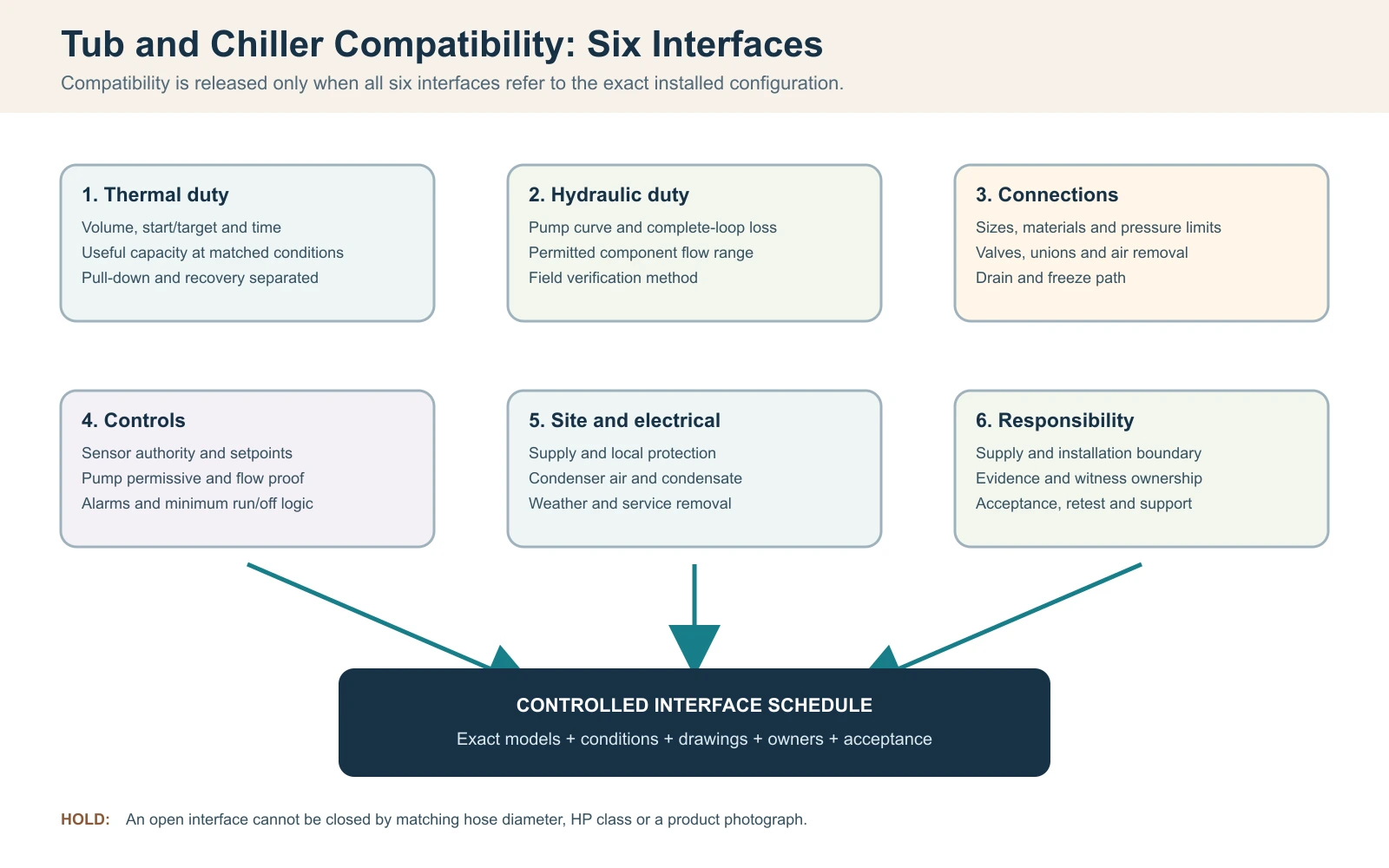
Direct answer: Match a cold plunge tub with a chiller by closing six interfaces for the exact installed system: thermal duty, hydraulic operating point, physical connections, control logic, electrical/site conditions and responsibility for installation and acceptance. Start with the real operating water volume, start and target temperatures, required pull-down and recovery windows, condenser-intake ambient and the complete water loop. Then verify condition-linked cooling capacity and a pump operating point that keeps every series component inside its permitted flow range.
Connector size, tub volume and chiller horsepower are useful screening fields, but none proves compatibility by itself. A defensible release record identifies the exact tub, chiller, pump, filter/treatment components, controls and site assumptions, then records what was verified, what remains open and what would stop release.
Page scope: this article owns vessel-to-chiller interface matching. It uses only enough thermal and capacity logic to test that interface. Full project cooling-duty calculations belong to the Cold Plunge Thermal Engineering and Chiller Sizing Guide; horsepower versus useful cooling capacity belongs to Cold Plunge Chiller HP vs Cooling Capacity. Exact model connections, operating limits and ratings must come from the approved data for the ordered configuration.
On this page
- Close Six Interfaces Before Calling the Tub and Chiller Compatible
- Define the Complete Water Loop and the Real Operating Volume
- Check Thermal Duty Before Approving the Chiller Match
- Verify Useful Cooling Capacity at the Same Conditions
- Find the Pump Operating Point Across the Complete Loop
- Coordinate Flow Limits, Priming, Air Removal and Freeze Drain-Down
- Match Sensors, Setpoints, Pump Permissives and Alarm Logic
- Verify Condenser Air, Weather, Condensate and Service Space
- Collect Synchronized Data Before Assigning a Performance Cause
- Assign Interface Responsibility and Grade the Evidence
- Commission Against a Written Boundary, Then Retest the Cause
- Issue a Controlled Interface Schedule and Final Go/No-Go Record
Close Six Interfaces Before Calling the Tub and Chiller Compatible
For this matching workflow, treat a cold plunge tub and chiller as compatible only when six interfaces close together: thermal duty, water flow and pressure loss, physical connections, control logic, electrical/site conditions and service responsibility. Matching hose diameters or buying a larger horsepower class does not prove compatibility. The release decision should identify the exact tub, chiller, pump, filter, treatment components and control revision rather than two category names.
Start with a one-line operating requirement: actual water volume, start and target temperatures, allowed pull-down time, expected session pattern, condenser-intake ambient range and indoor or outdoor location. Then draw the complete loop and name every supplied and site-installed component. A compatible proposal must show that useful cooling capacity is available at the declared conditions and that the pump can move water through the complete installed resistance while remaining inside each component’s permitted flow range.
Tub and chiller compatibility release record
| Interface | Question that must close | Release evidence |
|---|---|---|
| Thermal | Can useful output meet pull-down and recovery duties at the design condition? | Condition-linked capacity data and bounded calculation |
| Hydraulic | Does the pump duty point fall inside the exchanger and treatment flow limits? | Pump curve, pressure-loss basis and field verification method |
| Connections | Are sizes, materials, valves, unions, drain and air-removal paths coordinated? | Approved loop and connection drawing |
| Controls | Which device commands the pump and compressor, and what stops unsafe operation? | Sequence of operation, alarm and interlock schedule |
| Site/electrical | Are power, condenser air, weather, drainage and service removal workable? | Site plan and qualified local review where required |
| Responsibility | Who supplies, installs, verifies and supports each interface? | Approved responsibility and acceptance matrix |
Release rule: an open interface remains an engineering hold, even when both products operate separately. Do not use unapproved adapters, bypass controls or unapproved pump changes to force a field fit after delivery.
Define the Complete Water Loop and the Real Operating Volume
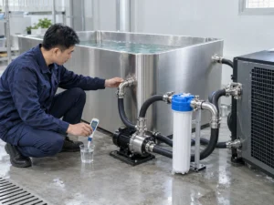
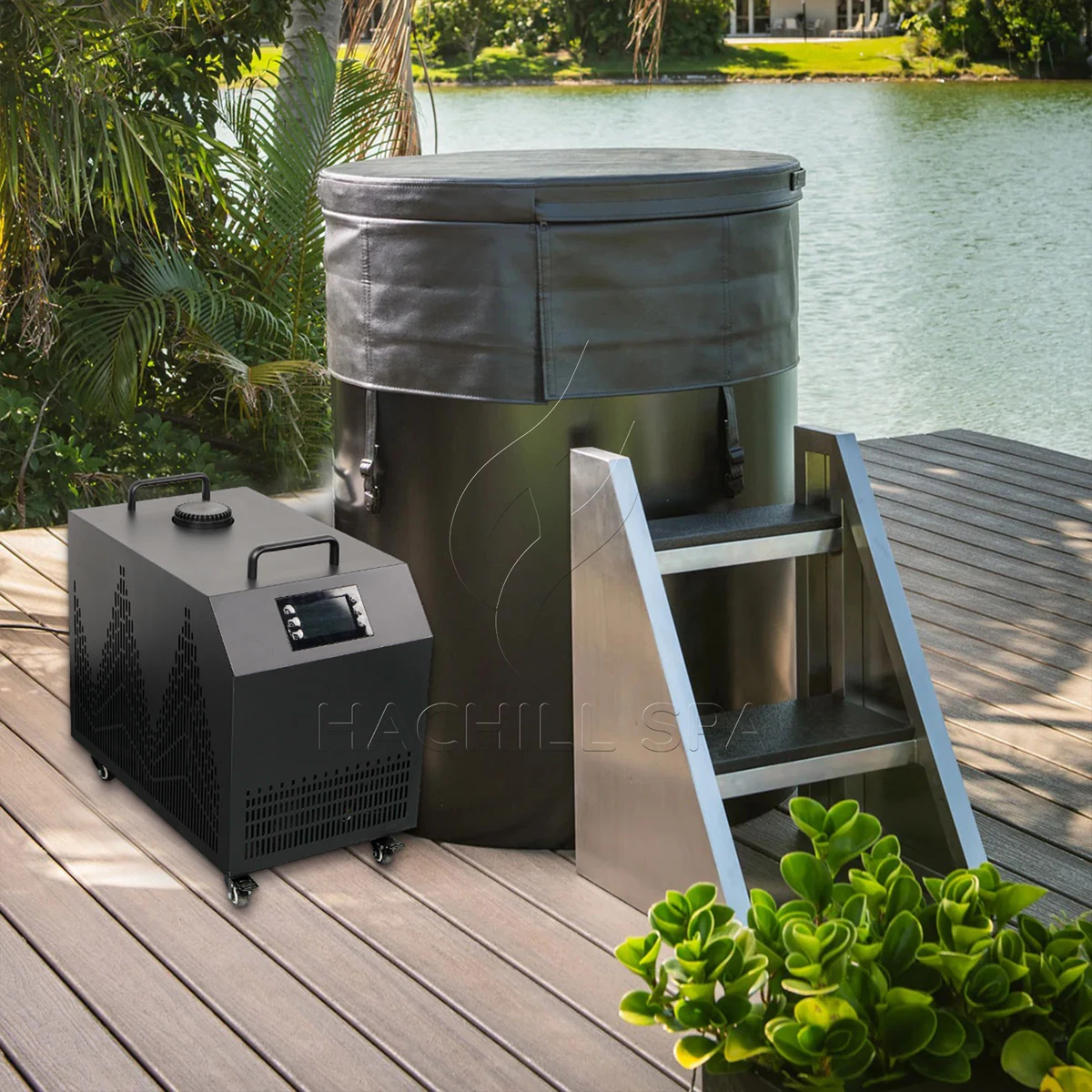
Mark the water path from the tub outlet through strainers, pump, filter, treatment components and heat exchanger, then back to the tub. Include isolation valves, check valves, elbows, reducers, flexible hose, vertical rises and any bypass. Component order affects priming, air removal, service access and what happens when a filter loads. A photograph of two hose tails does not show the installed hydraulic circuit.
Use operating water volume, not the vessel’s maximum geometric capacity. The volume depends on the approved waterline, internal displacement, user displacement and whether external pipework or a buffer adds material water volume. Measure a fill with a suitable meter when approved model data is unavailable, and record the measurement method. Guessing from external dimensions can overstate or understate the thermal mass because seats, wall thickness and freeboard are not water.
Freeze the configuration revision with the loop. A distributor may pair a tub from one supplier with a separate chiller, pump and sanitation skid. Each component can be individually suitable yet incompatible as a loop if connection materials, pressure ratings, required flows or control assumptions differ. Record what is in the crate, what the installer supplies and which drawing controls the final arrangement.
Check Thermal Duty Before Approving the Chiller Match
The tub/chiller match still needs a thermal gate, but the compatibility check should stop short of becoming a second full sizing workflow. Record the actual operating water volume, initial and target temperatures, allowed pull-down time, expected recovery interval, condenser-intake ambient, cover state and representative user schedule. The pairing remains open until the selected chiller has useful cooling evidence that applies to those conditions.
For a transparent water-only screen, sensible heat can be estimated with Q = m x cp x Delta T. The U.S. Department of Energy thermodynamics handbook uses the same sensible-heat relationship, and liquid-water heat capacity varies with temperature rather than being one immutable constant. For an illustrative 400 L operating volume, approximated as 400 kg of water, cooling from 22 C to 10 C with cp = 4.186 kJ/kg-K gives about 5.58 kWh thermal of stored water energy. If a verified net useful output averaged 2.4 kW across the relevant conditions, the ideal water-only time would be about 2.33 hours.
This calculation is a screening bridge between the tub duty and the chiller evidence, not a HACHILL performance promise. It excludes heat entering through the vessel, exposed water, pipework and room; pump heat; solar gain; control cycling; and changes in available capacity as water and ambient conditions move. Do not add a generic percentage margin simply to make the result look complete. Carry unresolved heat gains into the dedicated thermal-sizing workflow or close them with controlled complete-system testing.
Thermal compatibility gate
| Field | Minimum match evidence | Keep the pairing open when |
|---|---|---|
| Operating water volume | Approved waterline or measured fill, with included external volume stated | Only nominal vessel capacity or external dimensions are known |
| Pull-down duty | Start/target temperatures and allowed time | The quotation gives only a generic “cools to” claim |
| Recovery duty | Representative user/refill event and required recovery window | An overnight pull-down result is being used as a busy-use proxy |
| Ambient/cover state | Condenser-intake condition and declared cover/open state | The capacity evidence was produced at unmatched conditions |
| Capacity evidence | Useful output for the exact model/configuration at relevant conditions | Only HP, input power or an unqualified maximum is available |
Verify Useful Cooling Capacity at the Same Conditions
Horsepower, compressor input and useful cooling output answer different questions. For compatibility, compare the tub duty with cooling capacity stated for the exact chiller configuration at relevant water temperature, condenser-intake ambient, flow and electrical supply. A single warm-water or favorable-ambient point may be valid evidence for that point while still being insufficient near the project target.
Keep the test boundary attached to every number. Ask whether the stated capacity represents the refrigeration unit alone or the complete supplied package, and whether pump, fan, heat exchanger and control behavior are included in the declared boundary. Two quotations can show the same capacity value while describing different conditions or different parts of the system.
A larger unit is not automatically a better match. Depending on the equipment and control design, excessive capacity can create a larger electrical and condenser-air requirement, move the hydraulic requirement, or produce short cycling when the active load falls below the unit’s controllable range. The correct selection must satisfy the most demanding valid duty while remaining inside the exact model’s permitted operating envelope.
Capacity evidence needed for a tub/chiller match
| Supplier field | Use it for | Do not substitute |
|---|---|---|
| Useful cooling capacity | Heat-removal rate at declared water, ambient, flow and supply conditions | HP class or compressor input |
| Pull-down result | Evidence only when volume, start/target, ambient, cover and configuration are declared | An unqualified hours-to-temperature claim |
| Operating envelope | Permitted water/ambient/flow boundaries for the ordered revision | One catalogue test point |
| Electrical input | Site load and efficiency analysis within a defined boundary | Cooling output |
| Control/minimum-load behavior | Whether the selected unit can remain stable as load falls | The assumption that more capacity is always safer |
Find the Pump Operating Point Across the Complete Loop
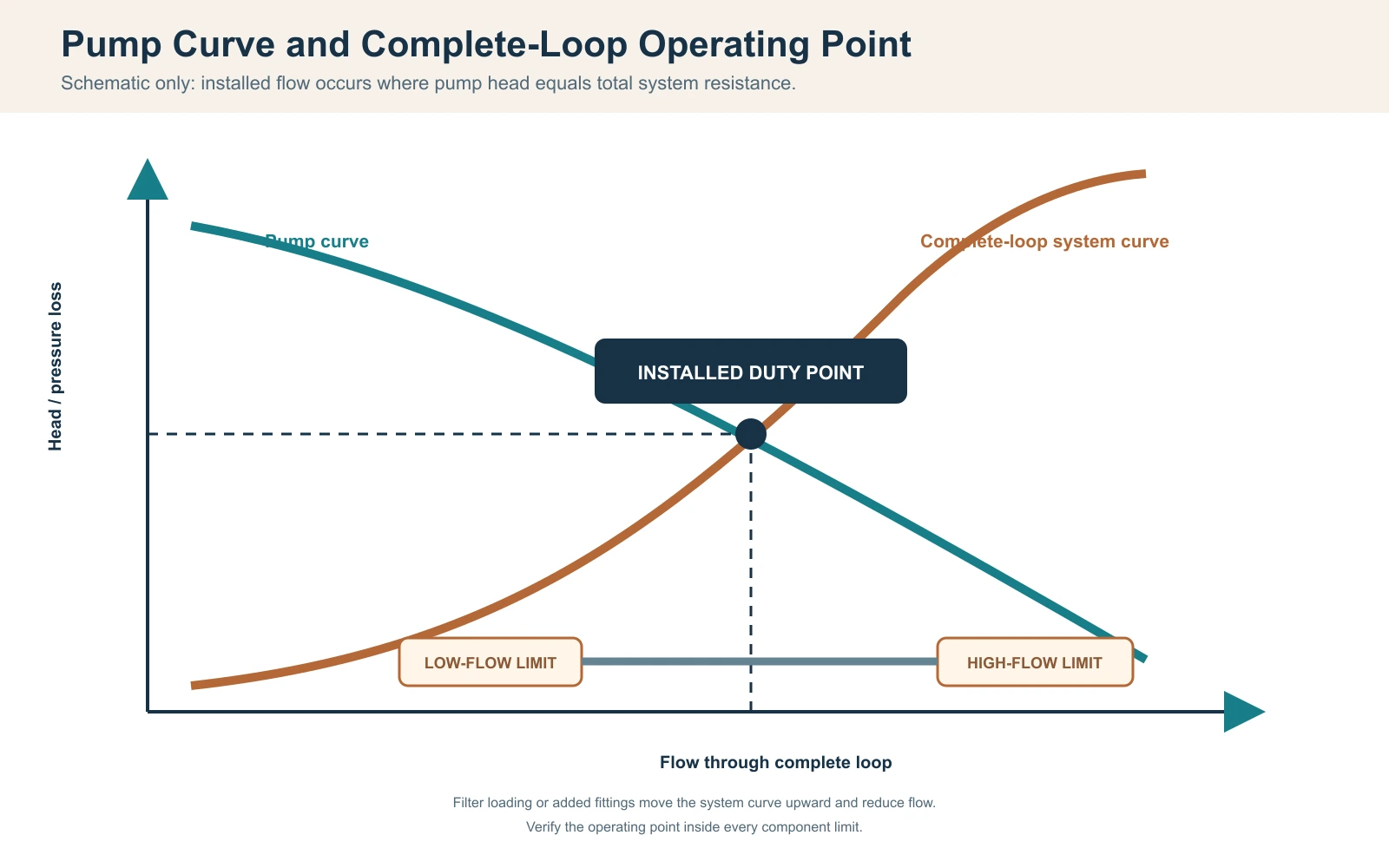
For a fixed-speed pump without an active flow-control device, the installed operating point is where the pump curve intersects the system-resistance curve; the Hydraulic Institute’s combined pump and system curve guidance documents this relationship. Variable-speed control or an active control valve can shift or hold the operating point, but the pump capability and complete-system resistance still have to be reconciled. Pump maximum flow, commonly stated at little or no head, cannot be treated as installed flow. Build resistance from straight pipe, hose, fittings, valves, filter or strainer, treatment devices and the chiller heat exchanger at the design flow. Include the service condition: a clean filter may pass commissioning while a loaded filter later moves the system outside the chiller’s permitted flow range.
Use manufacturer pressure-loss data for components when available. For pipework, a qualified designer can calculate friction and minor losses using the approved diameter, length, material and fittings. Static elevation in a closed circulating loop is not handled the same way as an open lift, but priming and trapped air still matter. Do not add or omit elevation terms without defining the actual arrangement.
A water-side heat-balance check can support commissioning: Qdot = mass flow x cp x Delta T. For an illustrative verified flow of 30 L/min, water mass flow is about 0.5 kg/s. If a stable, calibrated inlet-to-outlet difference is 1.0 K, the water-side transfer is approximately 0.5 x 4.186 x 1.0 = 2.09 kW. This result is sensitive to flow accuracy, sensor bias, mixing, time alignment and transient storage; it is not valid when readings are taken at different times or locations.
Hydraulic operating-point record
| Item | Design evidence | Field evidence |
|---|---|---|
| Pump | Curve for exact model, speed and frequency | Operating mode and verified duty indication |
| Pipe and hose | Inside diameter, length, material and routing | Installed revision and kink/restriction check |
| Fittings and valves | Count, type and position | As-installed valve-position record |
| Filter/treatment | Clean and service pressure loss | Condition and pressure indication where provided |
| Heat exchanger | Permitted flow range and pressure loss | Flow method, inlet/outlet temperature and alarms |
| Uncertainty | Instrument range and required accuracy | Identity, verification status, location and timestamp |
Coordinate Flow Limits, Priming, Air Removal and Freeze Drain-Down
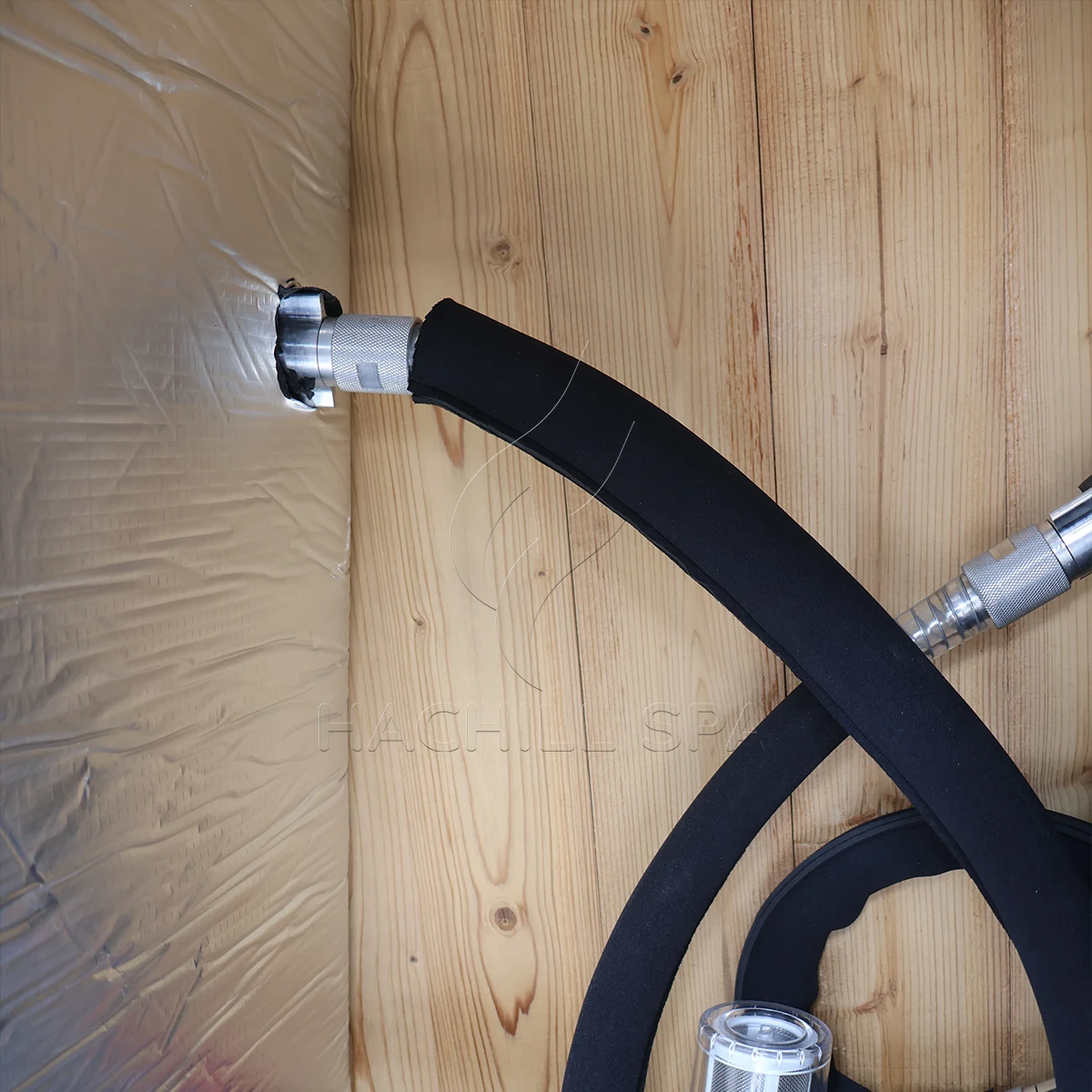
Both low and excessive flow can disqualify a match. Low flow can reduce water-side heat transfer and may trigger flow or freeze protection; flow above a component’s approved limit can exceed heat-exchanger, filter or connection ratings and can increase pressure drop, noise or velocity-related wear depending on the design. Confirm the permitted range for every series component, then select an operating point inside the narrowest applicable range with margin for normal filter loading.
Place the pump and valves so the circuit can be filled, vented and primed by the approved method. A frequent start-up problem occurs when the pump contains air: it sounds active but does not establish circulation, so the chiller reports low flow or the pump runs dry. Check water level, valve position, suction leaks, trapped high points and the manual’s priming steps. Never defeat a flow switch to force compressor operation.
Engineering scenario: Matching hose sizes, but repeated low-flow alarms
Observed problem: The tub and chiller both use the same nominal connector size, yet the installed system trips after the filter is added.
Likely cause: Selection compared connector diameter but omitted hose length, elbows, filter pressure loss and the pump curve.
How to check: Freeze the installed loop, verify valve and filter condition, calculate the resistance and measure flow by an approved method.
Prevention or corrective path: Select the pump from the complete-loop duty point and retain a service margin without exceeding component limits.
Outdoor or unheated installations need a defined freeze strategy. Identify every low point, trapped volume and component that requires draining or protected circulation. A drain fitting on the tub does not automatically empty the chiller, heat exchanger, pump or external hose. Use model instructions and climate-specific professional design; freezing damage cannot be prevented by a generic blog procedure.
Match Sensors, Setpoints, Pump Permissives and Alarm Logic
Decide which sensor controls the system and where it measures. A sensor inside the chiller may see water different from the mixed bulk tub, especially at low flow or immediately after a user enters. Record sensor placement, mixing assumptions, displayed resolution and any offset procedure. Do not move a sensor after acceptance without revising the test basis.
The sequence of operation should state when the circulation pump starts, what proves flow, when the compressor is permitted, how setpoint deadband is applied, and what happens after an alarm or power interruption. If the tub controller and external chiller both command temperature, conflicting setpoints can create unstable cycling. Choose one controlling authority or document a coordinated sequence.
Electrical matching includes voltage, frequency, phase, rated current, starting behavior, disconnect and protective requirements for the destination. Final conductor sizing, overcurrent protection, disconnect, grounding/bonding and any GFCI or RCD requirement must follow the ordered equipment data, manufacturer’s instructions and applicable local electrical rules, with regulated work completed by qualified local professionals. For U.S. workplaces, OSHA 1910.333 defines safety-related work practices and restricts energized work to qualified persons. A plug adapter does not correct incompatible voltage or frequency.
Engineering scenario: Correct capacity, unstable temperature
Observed problem: The water reaches target, but the compressor starts and stops frequently and the displayed temperatures disagree.
Likely cause: Two controllers use different setpoints, the sensor sees poorly mixed return water, or minimum run/off logic was not coordinated.
How to check: Log both displays, pump state, compressor state, sensor locations and control setpoints on one timeline.
Prevention or corrective path: Approve a single sequence of operation, sensor authority and alarm response before production or site wiring.
Verify Condenser Air, Weather, Condensate and Service Space
An air-cooled chiller rejects tub heat plus compressor input into the surrounding air; ASHRAE’s condenser guidance describes condenser heat rejection as the evaporator load plus compressor energy input. The intake needs air within the approved ambient range, and the hot discharge must not recirculate into the intake. A unit placed inside a tight cabinet may have enough visual clearance for hoses but insufficient free area for airflow, causing reduced output or high-pressure protection.
Measure ambient at the condenser intake during a performance test, not at a distant room thermostat. Record solar exposure, nearby exhausts, walls, screens and other equipment that can change intake conditions. For indoor plant areas, coordinate ventilation or heat rejection with the building team. For outdoor placement, confirm enclosure suitability, rain and debris exposure, drainage, wind effects and any low-temperature operating boundary from the exact manual.
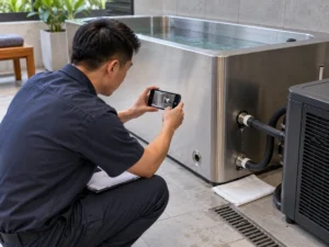
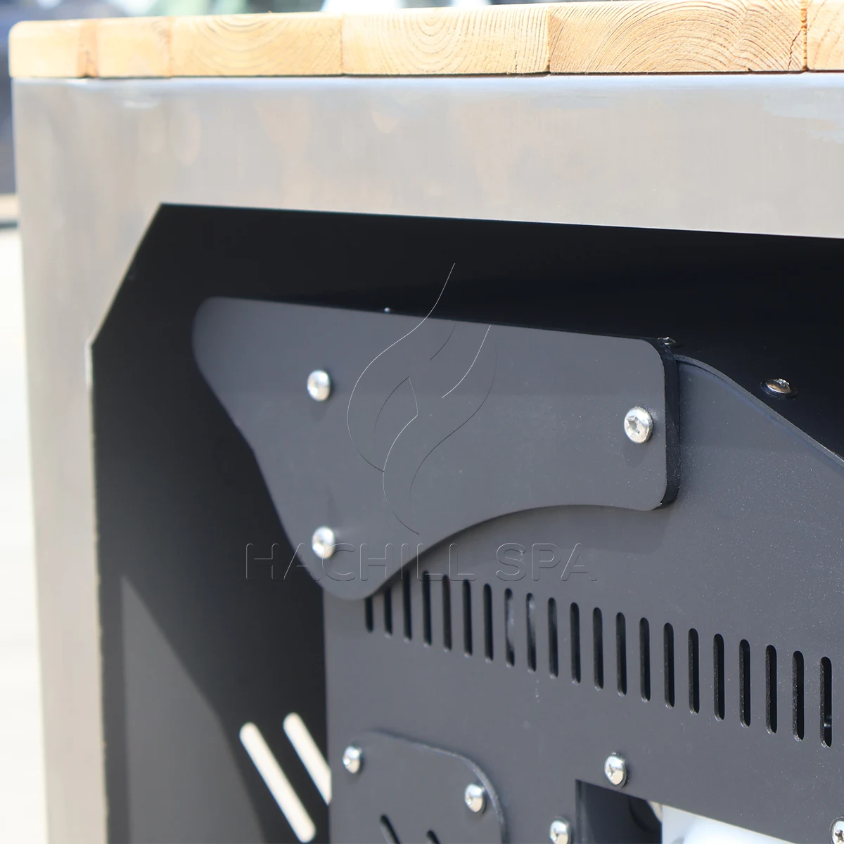
Cold pipes and components may produce condensation. Route it so water cannot create slip exposure, damage finishes or reach electrical equipment. Maintain access to filters, valves, panels and any component that must be removed. A service panel visible in a product image does not prove that it can open after the unit is built into joinery.
Collect Synchronized Data Before Assigning a Performance Cause
Collect one synchronized record for the complete system. Identify the exact tub, chiller, pump, filter and control revisions; actual operating volume; sensor identity and placement; flow verification method; condenser-intake ambient; water inlet, outlet and mixed bulk temperatures; pump/compressor state; filter condition; cover state; electrical boundary; timestamps and deviations. Unsynchronized readings cannot support a reliable water-side capacity calculation.
Tub and chiller commissioning data log
| Record point | Thermal/environment data | Hydraulic/control data | Configuration evidence |
|---|---|---|---|
| Before fill | Source-water temperature and design ambient | Valve, drain and filter state | Approved drawings and component identities |
| Start | Mixed bulk, inlet/outlet and condenser-intake temperatures | Verified flow method, pump mode and setpoint | Water volume, supply and cover state |
| Fixed intervals | Same sensors and timestamps | Pump/compressor/fan state and alarms | Openings, solar or other deviations |
| Session recovery | Before/after mixed bulk and ambient | Control state and circulation continuity | User count, timing and water loss |
| Endpoint | Final mixed bulk and intake ambient | Stable flow and control transition | Witness, instrument and exception references |
Classify a shortfall before assigning responsibility. A thermal-selection cause may involve unmatched capacity conditions or omitted heat gain. A hydraulic cause may involve low flow, a loaded filter or air. A control cause may involve sensor position, interlocks or cycling. A site cause may involve recirculated condenser air, solar load or incorrect electrical supply. A data cause may involve unverified flow, sensor bias or missing timestamps.
Stop the test and use qualified service for repeated electrical or pressure protection, damaged wiring, refrigerant or oil leakage indication, smoke, overheating, a pump running without water, uncontrolled freezing or leakage at electrical interfaces. Operators may verify visible conditions allowed by the manual; they must not open electrical or refrigeration enclosures or bypass protection.
Assign Interface Responsibility and Grade the Evidence
Tub and chiller interface responsibility matrix
| Interface | Equipment supplier | Buyer/operator | Installer/local professional | Close-out evidence |
|---|---|---|---|---|
| Duty basis | Review feasibility and declare open inputs | Own use pattern and target duty | Review site implications | Approved operating brief |
| Thermal selection | Provide condition-linked model evidence | Approve required times and conditions | Verify installed boundary | Selection record and acceptance basis |
| Hydraulic loop | Provide component limits and connections | Approve supplied/site scope | Design/install/verify site circuit | Loop drawing and flow record |
| Controls | Provide sequence, alarms and interfaces | Approve operating authority | Complete permitted site integration | Control schedule and functional test |
| Electrical/site | Provide exact model data and clearances | Provide destination and facility inputs | Qualified design and approval | Site-release records |
| Commissioning | Support product-specific checks | Provide operator and witness | Verify installation and regulated work | Signed result, deviations and retest status |
Grade evidence by applicability. An order-specific witnessed test at agreed conditions is strongest for contractual acceptance. Independent or accredited evidence can support compliance or performance only within its stated model and scope. Model-specific manufacturer data with method and conditions supports engineering selection. Transparent calculations support screening. Generic brochures, HP labels and photographs support discovery only.
Use hold points before ordering site penetrations, releasing production, dispatching the system and opening it to users. A standard or certification reference describes a scope; it does not prove that the ordered HACHILL model, voltage or configuration holds that approval. Keep any required destination evidence open until the responsible reviewer confirms exact applicability.
Commission Against a Written Boundary, Then Retest the Cause
Write acceptance before the field test. State configuration, water volume, start and target conditions, allowed time or water-side capacity point, condenser-intake ambient band, flow range and verification method, filter condition, cover and solar state, electrical boundary, sensor locations, instrument status, control mode, endpoint and witnesses. Predefine what makes a run invalid and what deviation can be accepted.
Compatibility acceptance and dispute register
| Observed dispute | Evidence required | Disposition |
|---|---|---|
| Pull-down is slow | Matched volume, temperatures, ambient, flow, controls and heat gains | Separate selection, hydraulic, control, site and data causes |
| Flow is disputed | Pump curve, installed resistance, filter state and verification method | Correct the loop or method; do not infer flow from appearance |
| Displays disagree | Sensor identity, position, mixing and verification status | Correct the measurement basis and retest |
| Chiller trips | Alarm history, airflow, flow, supply and manual boundaries | Stop unsafe work; qualified diagnosis before reset/retest |
| Scope is incomplete | Approved interface schedule, drawing and packing record | Hold installation or acceptance until responsibility closes |
| Conditions changed | Deviation log and pre-agreed tolerance | Invalidate or disposition the run before judging performance |
A retest should change only the identified cause and preserve the other conditions as far as practical. If flow was unverified, correct the method and repeat; if condenser air was recirculating, correct the site condition and repeat; if sensors were biased, verify or replace them and repeat. Record who authorizes the retest and who bears its cost under each cause category.
Engineering scenario: The chiller appears undersized only after installation
Observed problem: Supplier data suggested adequate output, but field pull-down is slow.
Likely cause: The site test uses hotter condenser intake, lower flow and an uncovered tub while the selection basis used different conditions.
How to check: Reconcile every acceptance input and classify thermal, hydraulic, control, site and data deviations.
Prevention or corrective path: Freeze condition-linked evidence and the commissioning boundary before PO release, then retest only after the cause is controlled.
Issue a Controlled Interface Schedule and Final Go/No-Go Record
The final compatibility record should fit on a controlled schedule: exact models and revisions, operating water volume, thermal duties, capacity evidence and conditions, pump operating point, component flow limits, connection sizes and materials, loop drawing, control sequence, electrical supply, condenser-air boundary, freeze and drain method, service clearances, responsibility owners and acceptance tests. Every open item needs an owner, due date and release effect.
For an RFQ, send water volume, initial and target temperatures, pull-down and recovery times, users and schedule, indoor/outdoor location, ambient range, pipe route, filter and treatment scope, available power, control integration, destination market and required evidence. Ask suppliers to return inclusions, exclusions and assumptions in the same schedule so quotations can be compared without filling gaps with sales language.
- Freeze the exact tub volume and complete water-loop revision.
- Separate pull-down, holding and session recovery duties.
- Match useful cooling output at relevant water, ambient, flow and supply conditions.
- Plot or document the pump duty point against full-loop resistance.
- Confirm component flow ranges, priming, air removal and freeze drainage.
- Approve sensor authority, pump permissives, alarms and anti-short-cycle logic.
- Assign every supplied and site-installed interface.
- Write acceptance, deviation, stop, retest and dispute rules before shipment.
HACHILL can review a product-family or model pairing when the buyer supplies these inputs. Any unverified model value, certification scope or site assumption should remain open until supported by order-specific data; the review does not replace licensed electrical, structural, public-health or refrigeration work.
Frequently asked questions
What size chiller do I need for a cold plunge?
There is no reliable answer from tub volume alone. For this matching page, the required inputs are operating volume, start and target temperatures, pull-down and recovery windows, condenser-intake ambient, user schedule, cover/insulation state and hydraulics. Use the dedicated thermal-sizing guide to calculate project duty, then return here to close the tub/chiller interfaces with condition-linked model data.
Is chiller horsepower the same as cooling capacity?
No. Horsepower may describe a compressor or marketed size class, while useful cooling capacity depends on the complete refrigeration system and test conditions. Compare heat-removal capacity at stated water and ambient temperatures.
Why can a cold plunge cool more slowly outdoors?
Warmer condenser-intake air, solar heat gain, discharge-air recirculation, exposed pipework and weak insulation or cover control can increase the system load or reduce available chiller output. Actual performance also depends on flow, filter condition and the exact unit’s operating envelope.
Can the circulation pump be selected by maximum flow?
No. Maximum or zero-head flow does not show the installed duty point. Pipe, fittings, filter and heat exchanger create pressure loss, while static elevation must be treated according to the actual open/closed circuit arrangement. Use the exact pump curve, the complete-system resistance and the chiller’s approved flow range.
What should a chiller commissioning record include?
Record the exact tub/chiller/pump revision, operating water volume, synchronized water and condenser-intake temperatures, verified flow method, filter state, sensor locations, control setpoints, pump/compressor state, electrical supply boundary, timestamps, alarms and any deviations. Compare the run only with the pre-agreed acceptance basis.
Related HACHILL resources
Cold plunge product category
Use the product category to move from system-interface requirements to the appropriate cold-plunge product family.
Do cold plunge chillers run 24/7?
Use the duty-cycle guide when the open question is whether the chiller must run continuously or can cycle around a defined operating load.
Commercial cold plunge solutions
Use the commercial solution page when buyer type, venue and project scope are now more important than the tub-to-chiller interface itself.
Request a project quotation
Use the RFQ route once the interface schedule has enough closed inputs for a supplier review.
Reference basis
- U.S. Department of Energy, DOE-HDBK-1012/1-92: Thermodynamics, Heat Transfer, and Fluid Flow – Supports the sensible-heat and heat-transfer relationships used for screening calculations; it is not a cold-plunge performance standard.
- NIST Chemistry WebBook: Water – Reference thermophysical data showing that liquid-water heat capacity is temperature-dependent; project calculations should declare the property basis they use.
- Hydraulic Institute: Combined Pump & System Curves – Pump/system operating-point basis; exact pump curves, control mode and installed resistance still govern the real duty point.
- ASHRAE Handbook, Chapter 39: Condensers – Refrigeration condenser heat-rejection basis; exact equipment manuals govern ambient limits, airflow requirements and service clearances.
- OSHA 1910.333 – U.S. workplace safety-related electrical work-practice reference where applicable; it does not replace destination electrical design rules or the equipment manual.
Technical and safety boundary for How to Match a Cold Plunge Tub with a Chiller: Product manuals, approved drawings, applicable local building, electrical, public-health and accessibility requirements, and qualified trades take priority over general web guidance. This article does not claim certification or guaranteed site performance.
Turn the interface into a project brief
Send HACHILL the tub or shortlist, operating volume, temperature duty, ambient range, loop arrangement, treatment scope, power, destination and required records. The team can review a pairing while keeping unsupported fields open.