Guía técnica de bañeras de inmersión en frío
Compatibilidad técnica entre tina y enfriador para compradores, ingenieros de producto, instaladores y distribuidores.
Respuesta directa: Empareje una tina de inmersión en frío con un enfriador cerrando seis interfaces para el sistema instalado exacto: carga térmica, punto de operación hidráulico, conexiones físicas, lógica de control, condiciones eléctricas/del sitio y responsabilidad de instalación y aceptación. Comience con el volumen real de agua en operación, las temperaturas de inicio y objetivo, las ventanas requeridas de pull-down y recuperación, la temperatura ambiente de admisión del condensador y el circuito de agua completo. Luego verifique la capacidad de enfriamiento vinculada a las condiciones y un punto de operación de bomba que mantenga cada componente en serie dentro de su rango de caudal permitido.
El tamaño del conector, el volumen de la tina y la potencia del enfriador son campos útiles de cribado, pero ninguno prueba por sí solo la compatibilidad. Un registro de liberación defendible identifica la tina exacta, el enfriador, la bomba, los componentes de filtro/tratamiento, los controles y los supuestos del sitio, y luego registra qué se verificó, qué queda abierto y qué detendría la liberación.
Alcance de la página: este artículo aborda la coincidencia de interfaz entre cuba y chiller. Utiliza solo la lógica térmica y de capacidad suficiente para probar esa interfaz. Los cálculos completos de carga de enfriamiento del proyecto pertenecen a la Guía de ingeniería térmica y dimensionamiento de enfriadores para bañeras de inmersión en frío; la potencia en caballos de fuerza frente a la capacidad de enfriamiento útil pertenece a HP del enfriador de agua para baño de inmersión en frío frente a capacidad de enfriamiento. Las conexiones exactas del modelo, los límites de funcionamiento y las clasificaciones deben provenir de los datos aprobados para la configuración pedida.
En esta página
- Cierre seis interfaces antes de declarar compatibles la bañera y el enfriador
- Defina el circuito de agua completo y el volumen operativo real
- Verifique la carga térmica antes de aprobar la selección del enfriador
- Verifique la capacidad de enfriamiento útil en las mismas condiciones
- Encuentre el punto de funcionamiento de la bomba en todo el circuito
- Límites de flujo coordinados, purga, eliminación de aire y drenaje por congelación
- Coincidencia de sensores, puntos de consigna, permisivos de bomba y lógica de alarma
- Verificación del aire del condensador, clima, condensado y espacio de servicio
- Recopilación de datos sincronizados antes de asignar una causa de rendimiento
- Asignación de responsabilidad de interfaz y evaluación de la evidencia
- Puesta en marcha contra un límite escrito y repetición de la prueba de la causa
- Emisión de un programa de interfaz controlado y registro final de aprobación/rechazo
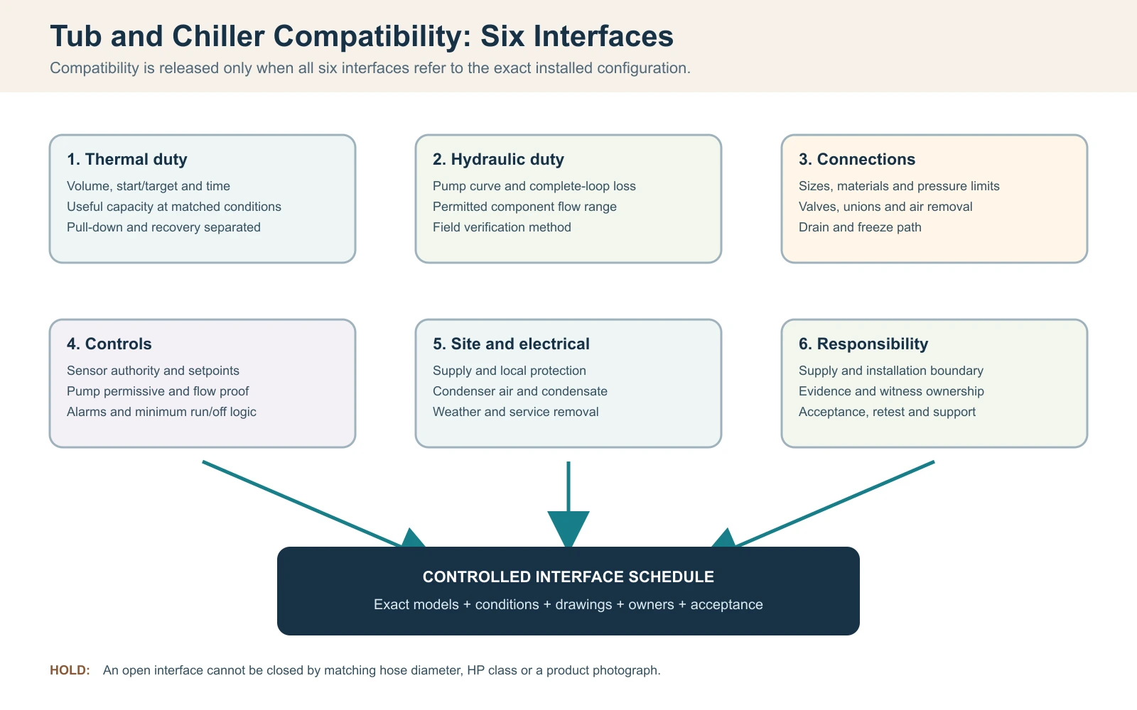
Cierre seis interfaces antes de declarar compatibles la bañera y el enfriador
Para este flujo de trabajo de emparejamiento, considere que una tina de inmersión en frío y un enfriador son compatibles solo cuando seis interfaces encajan entre sí: carga térmica, caudal de agua y pérdida de presión, conexiones físicas, lógica de control, condiciones eléctricas/del sitio y responsabilidad de servicio. Que coincidan los diámetros de las mangueras o comprar una clase de mayor potencia no demuestra compatibilidad. La decisión de liberación debe identificar la tina, el enfriador, la bomba, el filtro, los componentes de tratamiento y la revisión de control exactos, en lugar de dos nombres de categoría.
Comience con un requisito operativo de una línea: volumen de agua real, temperaturas inicial y objetivo, tiempo de enfriamiento permitido, patrón de sesión esperado, rango ambiente de entrada del condensador y ubicación interior o exterior. Luego dibuje el circuito completo y nombre cada componente suministrado e instalado en el sitio. Una propuesta compatible debe mostrar que la capacidad de enfriamiento útil está disponible en las condiciones declaradas y que la bomba puede mover el agua a través de la resistencia instalada completa mientras permanece dentro del rango de flujo permitido de cada componente.
Registro de liberación de compatibilidad de bañera y enfriador
| Interfaz | Pregunta que debe cerrarse | Evidencia de liberación |
|---|---|---|
| Térmico | ¿Puede la salida útil cumplir con las funciones de extracción y recuperación en la condición de diseño? | Datos de capacidad vinculados a la condición y cálculo acotado |
| Hidráulico | ¿El punto de funcionamiento de la bomba se encuentra dentro de los límites de flujo del intercambiador y del tratamiento? | Curva de la bomba, base de pérdida de presión y método de verificación en campo |
| Conexiones | ¿Están coordinados los tamaños, materiales, válvulas, uniones, drenaje y rutas de purga de aire? | Plano aprobado del circuito y de las conexiones |
| Controles | ¿Qué dispositivo controla la bomba y el compresor, y qué detiene el funcionamiento inseguro? | Secuencia de funcionamiento, programa de alarmas e interbloqueos |
| Sitio/eléctrico | ¿Son viables la alimentación eléctrica, el aire del condensador, el clima, el drenaje y la extracción para el servicio? | Plano del sitio y revisión local calificada cuando sea necesario |
| Responsabilidad | ¿Quién suministra, instala, verifica y brinda soporte para cada interfaz? | Matriz de responsabilidad y aceptación aprobada |
Regla de liberación: una interfaz abierta sigue siendo una retención de ingeniería, incluso cuando ambos productos funcionan por separado. No utilice adaptadores no aprobados, controles de derivación ni cambios de bomba no aprobados para forzar un ajuste en campo después de la entrega.
Defina el circuito de agua completo y el volumen operativo real
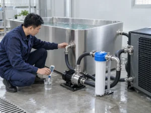
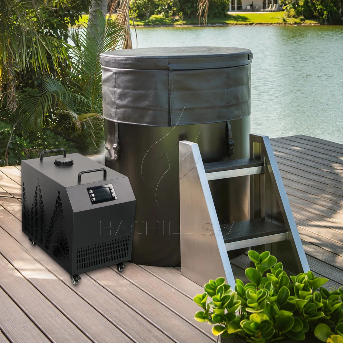
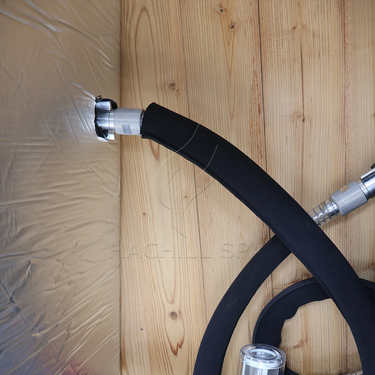
Marque el recorrido del agua desde la salida de la bañera a través de filtros, bomba, filtro, componentes de tratamiento e intercambiador de calor, y de vuelta a la bañera. Incluya válvulas de aislamiento, válvulas de retención, codos, reductores, manguera flexible, elevaciones verticales y cualquier derivación. El orden de los componentes afecta el cebado, la eliminación de aire, el acceso de servicio y lo que sucede cuando un filtro se carga. Una fotografía de dos racores de manguera no muestra el circuito hidráulico instalado.
Utilice el volumen de agua operativo, no la capacidad geométrica máxima del recipiente. El volumen depende de la línea de flotación aprobada, el desplazamiento interno, el desplazamiento del usuario y si las tuberías externas o un amortiguador añaden volumen de agua material. Mida el llenado con un medidor adecuado cuando no se disponga de datos de modelo aprobados y registre el método de medición. Adivinar a partir de las dimensiones externas puede sobreestimar o subestimar la masa térmica porque los asientos, el grosor de la pared y el borde libre no son agua.
Congele la revisión de configuración con el circuito. Un distribuidor puede combinar una bañera de un proveedor con un enfriador, bomba y skid de saneamiento separados. Cada componente puede ser individualmente adecuado pero incompatible como circuito si los materiales de conexión, las clasificaciones de presión, los caudales requeridos o las suposiciones de control difieren. Registre lo que hay en el embalaje, lo que suministra el instalador y qué dibujo controla la disposición final.
Verifique la carga térmica antes de aprobar la selección del enfriador
La combinación cuba/chiller todavía necesita una puerta térmica, pero la verificación de compatibilidad no debería convertirse en un segundo flujo de trabajo completo de dimensionamiento. Registre el volumen de agua operativo real, las temperaturas inicial y objetivo, el tiempo de descenso permitido, el intervalo de recuperación previsto, el ambiente de entrada del condensador, el estado de la cubierta y el programa representativo de usuarios. La combinación permanece abierta hasta que el chiller seleccionado tenga evidencia útil de enfriamiento que aplique a esas condiciones.
Para una estimación transparente solo con agua, el calor sensible se puede estimar con Q = m x cp x Delta T. El manual de termodinámica del U.S. Department of Energy usa la misma relación de calor sensible, y la capacidad calorífica del agua líquida varía con la temperatura en lugar de ser una constante inmutable. Para un volumen operativo ilustrativo de 400 L, aproximado como 400 kg de agua, enfriando de 22 C a 10 C con cp = 4.186 kJ/kg-K da aproximadamente 5.58 kWh térmicos de energía almacenada en el agua. Si una salida neta útil verificada promediara 2.4 kW en las condiciones relevantes, el tiempo ideal solo para el agua sería de aproximadamente 2.33 horas.
Este cálculo es un puente de cribado entre la carga de la tina y la evidencia del enfriador, no una promesa de rendimiento de HACHILL. Excluye el calor que entra a través del recipiente, el agua expuesta, la tubería y la sala; el calor de la bomba; la ganancia solar; el ciclado del control; y los cambios en la capacidad disponible a medida que varían el agua y las condiciones ambiente. No añada un margen porcentual genérico solo para que el resultado parezca completo. Traslade las ganancias de calor no resueltas al flujo de trabajo dedicado de dimensionamiento térmico o ciérrelas con pruebas controladas del sistema completo.
Puerta de compatibilidad térmica
| Campo | Evidencia mínima de coincidencia | Mantenga abierto el emparejamiento cuando |
|---|---|---|
| Volumen de agua operativo | Nivel de agua aprobado o llenado medido, con el volumen externo incluido declarado | Solo se conocen la capacidad nominal del recipiente o las dimensiones exteriores |
| Servicio de enfriamiento inicial | Temperaturas de inicio/objetivo y tiempo permitido | La cotización solo ofrece una afirmación genérica de “enfría hasta” |
| Servicio de recuperación | Evento representativo de usuario/rellenado y ventana de recuperación requerida | Se está usando un resultado de enfriamiento nocturno como proxy de uso intensivo |
| Estado del ambiente/cubierta | Condición de la toma del condensador y estado declarado de cubierta o abierto | La evidencia de capacidad se produjo en condiciones no coincidentes |
| Evidencia de capacidad | Salida útil para el modelo/configuración exactos en condiciones relevantes | Solo se dispone de HP, potencia de entrada o un máximo no calificado |
Verifique la capacidad de enfriamiento útil en las mismas condiciones
La potencia en caballos de fuerza, la entrada del compresor y la salida de enfriamiento útil responden a preguntas diferentes. Para la compatibilidad, compare la carga de la tina con la capacidad de enfriamiento indicada para la configuración exacta del enfriador a la temperatura del agua, el ambiente de entrada del condensador, el caudal y el suministro eléctrico relevantes. Un único punto de agua templada o ambiente favorable puede ser evidencia válida para ese punto, aunque siga siendo insuficiente cerca del objetivo del proyecto.
Mantenga el límite de prueba asociado a cada número. Pregunte si la capacidad indicada representa solo la unidad de refrigeración o el paquete completo suministrado, y si el comportamiento de la bomba, el ventilador, el intercambiador de calor y el control están incluidos en el límite declarado. Dos cotizaciones pueden mostrar el mismo valor de capacidad mientras describen condiciones diferentes o partes diferentes del sistema.
Una unidad más grande no es automáticamente una mejor opción. Según el diseño del equipo y del control, una capacidad excesiva puede crear un mayor requisito eléctrico y de aire del condensador, desplazar el requisito hidráulico o producir ciclos cortos cuando la carga activa cae por debajo del rango controlable de la unidad’. La selección correcta debe satisfacer el servicio válido más exigente mientras permanece dentro de la envolvente operativa permitida del modelo exacto’.
Evidencia de capacidad necesaria para emparejar bañera y enfriador
| Campo del proveedor | Úselo para | No sustituir |
|---|---|---|
| Capacidad de enfriamiento útil | Tasa de eliminación de calor en las condiciones declaradas de agua, ambiente, caudal y suministro | Clase de HP o entrada del compresor |
| Resultado de pull-down | Evidencia solo cuando se declaren volumen, inicio/objetivo, ambiente, cubierta y configuración | Una afirmación absoluta sobre horas hasta alcanzar la temperatura |
| Envolvente operativa | Límites permitidos de agua/ambiente/caudal para la revisión solicitada | Un punto de ensayo del catálogo |
| Entrada eléctrica | Análisis de carga y eficiencia del sitio dentro de un límite definido | Salida de refrigeración |
| Comportamiento de control/carga mínima | Si la unidad seleccionada puede mantenerse estable a medida que cae la carga | La suposición de que más capacidad siempre es más segura |
Encuentre el punto de funcionamiento de la bomba en todo el circuito
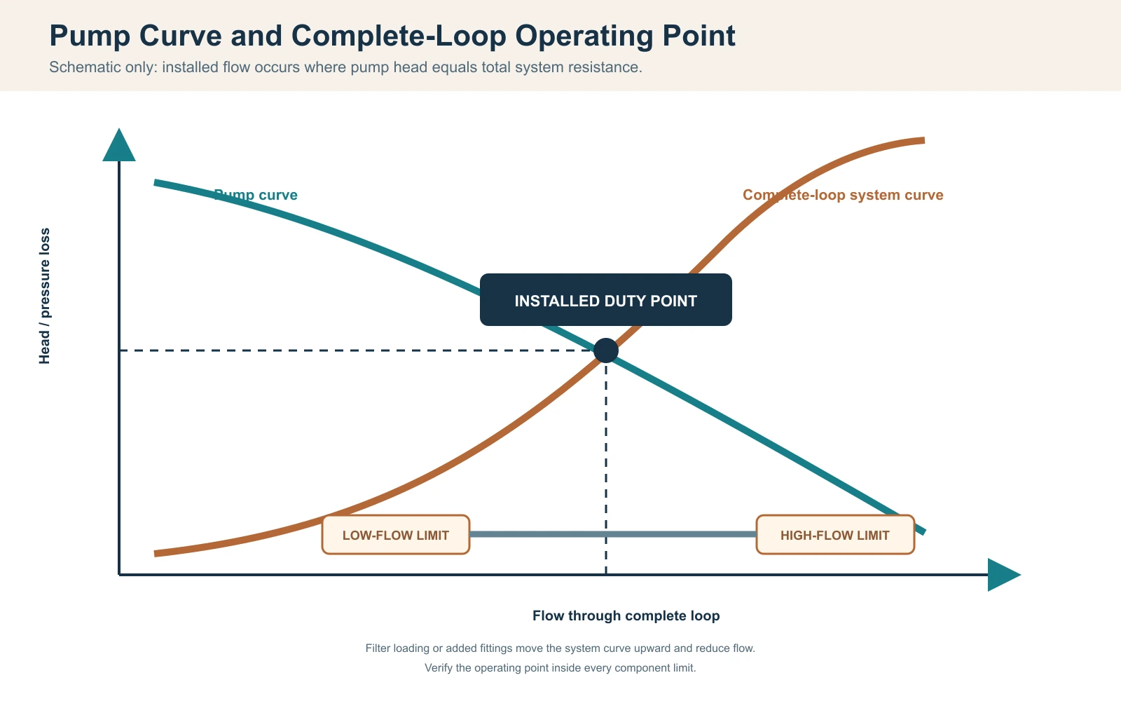
Para una bomba de velocidad fija sin un dispositivo de control de flujo activo, el punto de funcionamiento instalado es donde la curva de la bomba interseca la curva de resistencia del sistema; la guía de curvas combinadas de bomba y sistema del Hydraulic Institute documenta esta relación. El control de velocidad variable o una válvula de control activa pueden desplazar o mantener el punto de funcionamiento, pero la capacidad de la bomba y la resistencia del sistema completo aún deben conciliarse. El caudal máximo de la bomba, que suele indicarse con poca o ninguna altura manométrica, no puede tratarse como caudal instalado. Calcule la resistencia a partir de tubería recta, manguera, accesorios, válvulas, filtro o colador, dispositivos de tratamiento y el intercambiador de calor del enfriador al caudal de diseño. Incluya la condición de servicio: un filtro limpio puede pasar la puesta en marcha mientras que un filtro cargado después lleva el sistema fuera del rango de caudal permitido del enfriador.
Utilice los datos de pérdida de presión del fabricante para los componentes cuando estén disponibles. Para las tuberías, un diseñador cualificado puede calcular las pérdidas por fricción y las pérdidas menores utilizando el diámetro, la longitud, el material y los accesorios aprobados. La elevación estática en un circuito cerrado de circulación no se maneja de la misma manera que una elevación abierta, pero el cebado y el aire atrapado siguen siendo importantes. No añada ni omita términos de elevación sin definir la disposición real.
Una comprobación del balance térmico del lado del agua puede respaldar la puesta en marcha: Qdot = flujo másico x cp x Delta T. Para un flujo verificado ilustrativo de 30 L/min, el flujo másico de agua es de aproximadamente 0.5 kg/s. Si una diferencia calibrada y estable entre entrada y salida es de 1.0 K, la transferencia del lado del agua es de aproximadamente 0.5 x 4.186 x 1.0 = 2.09 kW. Este resultado es sensible a la precisión del flujo, el sesgo del sensor, la mezcla, la alineación temporal y el almacenamiento transitorio; no es válido cuando las lecturas se toman en momentos o lugares diferentes.
Registro del punto de funcionamiento hidráulico
| Artículo | Evidencia de diseño | Evidencia de campo |
|---|---|---|
| Bomba | Curva para el modelo, velocidad y frecuencia exactos | Indicación del modo de funcionamiento y del servicio verificado |
| Tubería y manguera | Diámetro interior, longitud, material y recorrido | Revisión de la revisión instalada y de pliegues/restricciones |
| Accesorios y válvulas | Cantidad, tipo y posición | Registro de la posición de las válvulas tal como se instalaron |
| Filtro/tratamiento | Pérdida de presión limpia y de servicio | Estado e indicación de presión cuando se proporciona |
| Intercambiador de calor | Rango de caudal permitido y pérdida de presión | Método de flujo, temperaturas de entrada/salida y alarmas |
| Incertidumbre | Rango del instrumento y precisión requerida | Identidad, estado de verificación, ubicación y marca de tiempo |
Límites de flujo coordinados, purga, eliminación de aire y drenaje por congelación
Tanto un caudal bajo como uno excesivo pueden descalificar una coincidencia. Un caudal bajo puede reducir la transferencia de calor del lado del agua y puede activar la protección de caudal o de congelación; un caudal por encima del límite aprobado de un componente puede superar los valores nominales del intercambiador de calor, el filtro o la conexión y puede aumentar la caída de presión, el ruido o el desgaste relacionado con la velocidad según el diseño. Confirme el rango permitido para cada componente de la serie y, a continuación, seleccione un punto de funcionamiento dentro del rango aplicable más estrecho con margen para la carga normal del filtro.
Coloque la bomba y las válvulas de modo que el circuito pueda llenarse, purgarse y cebarse mediante el método aprobado. Un problema frecuente de arranque ocurre cuando la bomba contiene aire: suena activa pero no establece circulación, por lo que el enfriador informa flujo bajo o la bomba funciona en seco. Verifique el nivel de agua, la posición de las válvulas, las fugas de succión, los puntos altos atrapados y los pasos de cebado del manual. Nunca anule un interruptor de flujo para forzar el funcionamiento del compresor.
Escenario de ingeniería: coincidencia de tamaños de manguera, pero alarmas repetidas de flujo bajo
Problema observado: La bañera y el enfriador utilizan el mismo tamaño nominal de conexión, pero el sistema instalado salta después de añadir el filtro.
Causa probable: La selección comparó el diámetro del conector pero omitió la longitud de la manguera, los codos, la pérdida de presión del filtro y la curva de la bomba.
Cómo comprobarlo: Congele el circuito instalado, verifique el estado de la válvula y del filtro, calcule la resistencia y mida el caudal mediante un método aprobado.
Prevención o vía correctiva: Seleccione la bomba según el punto de trabajo del circuito completo y conserve un margen de servicio sin superar los límites de los componentes.
Las instalaciones exteriores o sin calefacción necesitan una estrategia de congelación definida. Identifique cada punto bajo, volumen atrapado y componente que requiera drenaje o circulación protegida. Un desagüe en la bañera no vacía automáticamente el enfriador, el intercambiador de calor, la bomba o la manguera externa. Utilice las instrucciones del modelo y el diseño profesional específico para el clima; los daños por congelación no pueden prevenirse con un procedimiento genérico de blog.
Coincidencia de sensores, puntos de consigna, permisivos de bomba y lógica de alarma
Decida qué sensor controla el sistema y dónde mide. Un sensor dentro del enfriador puede ver agua diferente a la mezcla general de la bañera, especialmente con caudal bajo o inmediatamente después de que un usuario entre. Registre la ubicación del sensor, los supuestos de mezcla, la resolución mostrada y cualquier procedimiento de compensación. No mueva un sensor después de la aceptación sin revisar la base de la prueba.
La secuencia de funcionamiento debe indicar cuándo arranca la bomba de circulación, qué prueba el flujo, cuándo se permite el compresor, cómo se aplica la banda muerta del punto de consigna y qué ocurre después de una alarma o interrupción del suministro eléctrico. Si el controlador de la bañera y el enfriador externo controlan ambos la temperatura, los puntos de consigna conflictivos pueden provocar ciclos inestables. Elija una autoridad de control o documente una secuencia coordinada.
La correspondencia eléctrica incluye tensión, frecuencia, fase, corriente nominal, comportamiento de arranque, seccionamiento y requisitos de protección para el destino. El dimensionamiento final de conductores, la protección contra sobrecorriente, el seccionamiento, la puesta a tierra/conexión equipotencial y cualquier requisito de GFCI o RCD deben seguir los datos del equipo pedido, las instrucciones del fabricante’ y las normas eléctricas locales aplicables, con los trabajos regulados realizados por profesionales locales cualificados. Para lugares de trabajo en EE. UU., OSHA 1910.333 define prácticas de trabajo relacionadas con la seguridad y restringe el trabajo energizado a personas calificadas. Un adaptador de enchufe no corrige una tensión o frecuencia incompatibles.
Escenario de ingeniería: Capacidad correcta, temperatura inestable
Problema observado: El agua alcanza el objetivo, pero el compresor arranca y se detiene con frecuencia y las temperaturas mostradas no coinciden.
Causa probable: Dos controladores utilizan puntos de consigna diferentes, el sensor ve agua de retorno mal mezclada o la lógica de tiempo mínimo de funcionamiento/parada no se coordinó.
Cómo comprobarlo: Registre ambas pantallas, el estado de la bomba, el estado del compresor, las ubicaciones de los sensores y los puntos de consigna de control en una misma línea de tiempo.
Prevención o vía correctiva: Apruebe una única secuencia de operación, autoridad de sensores y respuesta de alarmas antes de la producción o el cableado en sitio.
Verificación del aire del condensador, clima, condensado y espacio de servicio
Un enfriador de agua refrigerado por aire disipa el calor de la bañera más la potencia del compresor al aire circundante; Guía de ASHRAE sobre condensadores describe la disipación de calor del condensador como la carga del evaporador más la energía consumida por el compresor. La entrada de aire debe estar dentro del rango ambiente aprobado, y la descarga caliente no debe recircular hacia la entrada. Una unidad colocada dentro de un armario cerrado puede tener suficiente espacio visual para las mangueras pero un área libre insuficiente para el flujo de aire, lo que provoca una reducción del rendimiento o la activación de la protección por alta presión.
Mida la temperatura ambiente en la entrada del condensador durante una prueba de rendimiento, no en un termostato de habitación distante. Registre la exposición solar, escapes cercanos, paredes, pantallas y otros equipos que puedan cambiar las condiciones de entrada. Para áreas de planta interiores, coordine la ventilación o el rechazo de calor con el equipo de construcción. Para ubicación exterior, confirme la idoneidad del recinto, la exposición a lluvia y escombros, el drenaje, los efectos del viento y cualquier límite operativo de baja temperatura del manual exacto.
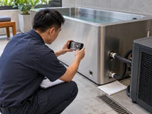
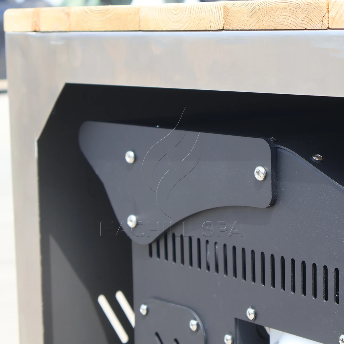
Las tuberías y componentes fríos pueden producir condensación. Diríjala de modo que el agua no pueda crear riesgo de resbalones, dañar acabados o alcanzar equipos eléctricos. Mantenga acceso a filtros, válvulas, paneles y cualquier componente que deba retirarse. Un panel de servicio visible en una imagen del producto no prueba que pueda abrirse después de que la unidad se integre en la carpintería.
Recopilación de datos sincronizados antes de asignar una causa de rendimiento
Recopile un registro sincronizado para el sistema completo. Identifique la tina, el enfriador, la bomba, el filtro y las revisiones de control exactos; el volumen operativo real; la identidad y ubicación del sensor; el método de verificación de flujo; la temperatura ambiente del condensador; las temperaturas de entrada, salida y masa mezclada del agua; el estado de la bomba/compresor; la condición del filtro; el estado de la cubierta; el límite eléctrico; marcas de tiempo y desviaciones. Las lecturas no sincronizadas no pueden respaldar un cálculo confiable de capacidad del lado del agua.
Registro de datos de puesta en marcha de la bañera y el enfriador de agua
| Punto de registro | Datos térmicos/ambientales | Datos hidráulicos/control | Evidencia de configuración |
|---|---|---|---|
| Antes del llenado | Temperatura del agua de fuente y ambiente de diseño | Estado de la válvula, el drenaje y el filtro | Planos aprobados e identidades de los componentes |
| Inicio | Temperaturas de masa mezclada, entrada/salida y entrada del condensador | Método de flujo verificado, modo de bomba y punto de consigna | Volumen de agua, suministro y estado de la cubierta |
| Intervalos fijos | Mismos sensores y marcas de tiempo | Estado de bomba/compresor/ventilador y alarmas | Aberturas, solar u otras desviaciones |
| Recuperación de sesión | Masa mezclada antes/después y ambiente | Estado de control y continuidad de circulación | Número de usuarios, tiempo y pérdida de agua |
| Punto final | Masa mezclada final y ambiente de entrada | Flujo estable y transición de control | Referencias de testigos, instrumentos y excepciones |
Clasifique una deficiencia antes de asignar responsabilidad. Una causa de selección térmica puede implicar condiciones de capacidad no coincidentes o ganancia de calor omitida. Una causa hidráulica puede implicar bajo flujo, un filtro cargado o aire. Una causa de control puede implicar posición del sensor, enclavamientos o ciclos. Una causa de sitio puede implicar aire de condensador recirculado, carga solar o suministro eléctrico incorrecto. Una causa de datos puede implicar flujo no verificado, sesgo del sensor o marcas de tiempo faltantes.
Detenga la prueba y use servicio calificado para protección eléctrica o de presión repetida, cableado dañado, indicación de fuga de refrigerante o aceite, humo, sobrecalentamiento, una bomba funcionando sin agua, congelación no controlada o fugas en interfaces eléctricas. Los operadores pueden verificar condiciones visibles permitidas por el manual; no deben abrir gabinetes eléctricos o de refrigeración ni omitir la protección.
Asignación de responsabilidad de interfaz y evaluación de la evidencia
Matriz de responsabilidad de interfaz de tina y enfriador
| Interfaz | Proveedor de equipos | Comprador/operador | Instalador/profesional local | Evidencia de cierre |
|---|---|---|---|---|
| Base del arancel | Revisar viabilidad y declarar entradas abiertas | Patrón de uso propio y arancel objetivo | Revisar implicaciones del sitio | Brief operativo aprobado |
| Selección térmica | Proporcionar evidencia del modelo vinculada a condiciones | Aprobar tiempos y condiciones requeridos | Verificar límite instalado | Registro de selección y base de aceptación |
| Circuito hidráulico | Proporcionar límites y conexiones de componentes | Aprobar el alcance suministrado/en sitio | Diseñar/instalar/verificar el circuito del sitio | Dibujo del circuito y registro de caudal |
| Controles | Proporcionar secuencia, alarmas e interfaces | Aprobar la autoridad operativa | Completar la integración permitida en el sitio | Programa de control y prueba funcional |
| Eléctrico/sitio | Proporcionar datos exactos del modelo y espacios libres | Proporcionar entradas de destino e instalaciones | Diseño calificado y aprobación | Registros de liberación del sitio |
| Puesta en marcha | Apoyar verificaciones específicas del producto | Proporcionar operador y testigo | Verificar la instalación y el trabajo regulado | Resultado firmado, desviaciones y estado de reprueba |
Clasifique la evidencia según su aplicabilidad. Una prueba presenciada específica del pedido en condiciones acordadas es la más sólida para la aceptación contractual. La evidencia independiente o acreditada puede respaldar el cumplimiento o el rendimiento solo dentro de su modelo y alcance declarados. Los datos del fabricante específicos del modelo con método y condiciones respaldan la selección de ingeniería. Los cálculos transparentes respaldan la selección preliminar. Los folletos genéricos, las etiquetas de HP y las fotografías respaldan solo el descubrimiento.
Utilice puntos de retención antes de ordenar penetraciones en el sitio, liberar la producción, despachar el sistema y abrirlo a los usuarios. Una referencia de norma o certificación describe un alcance; no prueba que el modelo, voltaje o configuración HACHILL pedido tenga esa aprobación. Mantenga abierta cualquier evidencia de destino requerida hasta que el revisor responsable confirme la aplicabilidad exacta.
Puesta en marcha contra un límite escrito y repetición de la prueba de la causa
Redacte la aceptación antes de la prueba de campo. Indique la configuración, el volumen de agua, las condiciones iniciales y objetivo, el tiempo permitido o el punto de capacidad del lado del agua, la banda de temperatura ambiente de entrada del condensador, el rango de caudal y el método de verificación, la condición del filtro, la cubierta y el estado solar, el límite eléctrico, las ubicaciones de los sensores, el estado del instrumento, el modo de control, el punto final y los testigos. Predefina qué hace que una ejecución sea inválida y qué desviación puede aceptarse.
Registro de aceptación de compatibilidad y disputas
| Disputa observada | Evidencia requerida | Disposición |
|---|---|---|
| El descenso es lento | Volumen, temperaturas, ambiente, caudal, controles y ganancias de calor coincidentes | Separar causas de selección, hidráulicas, de control, de sitio y de datos |
| El caudal está en disputa | Curva de bomba, resistencia instalada, estado del filtro y método de verificación | Corrija el circuito o el método; no infiera el caudal por apariencia |
| Las pantallas no coinciden | Identidad del sensor, posición, mezcla y estado de verificación | Corrija la base de medición y vuelva a probar |
| El enfriador se dispara | Historial de alarmas, flujo de aire, caudal, suministro y límites manuales | Detenga el trabajo inseguro; diagnóstico calificado antes de restablecer/reprobar |
| El alcance está incompleto | Programa de interfaz aprobado, dibujo y registro de empaque | Mantenga la instalación o aceptación en espera hasta que se cierre la responsabilidad |
| Condiciones cambiadas | Registro de desviaciones y tolerancia preacordada | Invalide o disponga de la ejecución antes de juzgar el rendimiento |
Una repetición de la prueba debe cambiar solo la causa identificada y preservar las demás condiciones en la medida de lo posible. Si el flujo no fue verificado, corrija el método y repita; si el aire del condensador estaba recirculando, corrija la condición del sitio y repita; si los sensores estaban sesgados, verifíquelos o reemplácelos y repita. Registre quién autoriza la repetición y quién asume su costo en cada categoría de causa.
Escenario de ingeniería: El enfriador parece subdimensionado solo después de la instalación
Problema observado: Los datos del proveedor sugirieron una salida adecuada, pero el enfriamiento en campo es lento.
Causa probable: La prueba en sitio utiliza una entrada de condensador más caliente, menor flujo y una tina descubierta, mientras que la base de selección usó condiciones diferentes.
Cómo comprobarlo: Reconcilie cada entrada de aceptación y clasifique las desviaciones térmicas, hidráulicas, de control, de sitio y de datos.
Prevención o vía correctiva: Congele la evidencia vinculada a las condiciones y el límite de puesta en marcha antes de la liberación de la orden de compra, luego repita la prueba solo después de que la causa esté controlada.
Emisión de un programa de interfaz controlado y registro final de aprobación/rechazo
El registro final de compatibilidad debe ajustarse a un cronograma controlado: modelos y revisiones exactos, volumen de agua operativo, cargas térmicas, evidencia y condiciones de capacidad, punto de operación de la bomba, límites de flujo de componentes, tamaños y materiales de conexión, dibujo del circuito, secuencia de control, suministro eléctrico, límite de aire del condensador, método de congelación y drenaje, espacios libres de servicio, responsables y pruebas de aceptación. Cada elemento abierto necesita un responsable, fecha de vencimiento y efecto de liberación.
Para una solicitud de cotización, envíe el volumen de agua, temperaturas inicial y objetivo, tiempos de enfriamiento y recuperación, usuarios y cronograma, ubicación interior/exterior, rango ambiental, ruta de tuberías, alcance de filtro y tratamiento, potencia disponible, integración de control, mercado de destino y evidencia requerida. Pida a los proveedores que devuelvan inclusiones, exclusiones y suposiciones en el mismo cronograma para que las cotizaciones puedan compararse sin llenar vacíos con lenguaje de ventas.
- Congele el volumen exacto de la tina y complete la revisión del circuito de agua.
- Separe las funciones de enfriamiento inicial, mantenimiento y recuperación de sesión.
- Iguale la salida de enfriamiento útil en las condiciones relevantes de agua, ambiente, caudal y suministro.
- Represente o documente el punto de trabajo de la bomba frente a la resistencia total del circuito.
- Confirme los rangos de caudal de los componentes, el cebado, la eliminación de aire y el drenaje por congelación.
- Apruebe la autoridad del sensor, los permisivos de la bomba, las alarmas y la lógica anti-ciclo corto.
- Asigne cada interfaz suministrada e instalada en sitio.
- Redacte las reglas de aceptación, desviación, parada, repetición de pruebas y disputas antes del envío.
HACHILL puede revisar un emparejamiento de familia de productos o modelo cuando el comprador proporciona estos datos. Cualquier valor de modelo no verificado, alcance de certificación o suposición de sitio debe permanecer abierto hasta que se respalde con datos específicos del pedido; la revisión no reemplaza el trabajo licenciado de ingeniería eléctrica, estructural, de salud pública o de refrigeración.
Preguntas frecuentes
¿Qué tamaño de enfriador necesito para una bañera de inmersión en frío?
No hay una respuesta fiable solo a partir del volumen de la tina. Para esta página de emparejamiento, las entradas requeridas son el volumen de operación, las temperaturas inicial y objetivo, las ventanas de enfriamiento inicial y recuperación, el ambiente de entrada del condensador, el calendario del usuario, el estado de la cubierta/aislamiento y la hidráulica. Use la guía dedicada de dimensionamiento térmico para calcular la carga del proyecto, y luego regrese aquí para cerrar las interfaces tina/enfriador con datos de modelo vinculados a las condiciones.
¿Es la potencia en caballos del enfriador lo mismo que la capacidad de enfriamiento?
N.º La potencia en caballos puede describir un compresor o una clase de tamaño comercial, mientras que la capacidad de enfriamiento útil depende del sistema de refrigeración completo y de las condiciones de prueba. Compare la capacidad de eliminación de calor a las temperaturas de agua y ambiente indicadas.
¿Por qué una bañera de inmersión fría puede enfriarse más lentamente en exteriores?
El aire más cálido de entrada al condensador, la ganancia solar de calor, la recirculación del aire de descarga, la tubería expuesta y el aislamiento débil o el control de la cubierta pueden aumentar la carga del sistema o reducir la capacidad disponible del enfriador. El rendimiento real también depende del flujo, el estado del filtro y la envolvente operativa exacta de la unidad’s.
¿Se puede seleccionar la bomba de circulación según el caudal máximo?
No. El flujo máximo o a altura cero no muestra el punto de trabajo instalado. La tubería, los accesorios, el filtro y el intercambiador de calor crean pérdida de presión, mientras que la elevación estática debe tratarse según la disposición real del circuito abierto/cerrado. Utilice la curva exacta de la bomba, la resistencia del sistema completo y el rango de flujo aprobado del enfriador.
¿Qué debe incluir un registro de puesta en marcha del enfriador?
Registre la revisión exacta de tina/enfriador/bomba, el volumen de agua de funcionamiento, las temperaturas sincronizadas del agua y de la entrada del condensador, el método de caudal verificado, el estado del filtro, las ubicaciones de los sensores, los puntos de consigna de control, el estado de la bomba/compresor, el límite del suministro eléctrico, las marcas de tiempo, las alarmas y cualquier desviación. Compare la ejecución solo con la base de aceptación previamente acordada.
Recursos relacionados de HACHILL
Categoría de producto: bañera de inmersión en frío
Utilice la categoría de producto para pasar de los requisitos de interfaz del sistema a la familia de productos de baño de inmersión en frío adecuada.
¿Los enfriadores de inmersión en frío funcionan con 24/7?
Utilice la guía de ciclo de trabajo cuando la cuestión abierta sea si el enfriador de agua debe funcionar de forma continua o puede ciclar en torno a una carga de trabajo definida.
Soluciones comerciales de inmersión fría
Utilice la página de solución comercial cuando el tipo de comprador, el establecimiento y el alcance del proyecto sean ahora más importantes que la propia interfaz entre la bañera y el enfriador de agua.
Solicitar presupuesto de proyecto
Utilice la vía de RFQ una vez que el cuadro de interfaces tenga suficientes datos cerrados para una revisión por parte del proveedor.
Base de referencia
- Departamento de Energía de EE. UU., DOE-HDBK-1012/1-92: Termodinámica, transferencia de calor y flujo de fluidos – Respalda las relaciones de calor sensible y transferencia de calor utilizadas para cálculos de selección preliminar; no es un estándar de rendimiento de inmersión en frío.
- NIST Chemistry WebBook: Agua – Datos termofísicos de referencia que muestran que la capacidad calorífica del agua líquida depende de la temperatura; los cálculos del proyecto deben declarar la base de propiedades que utilizan.
- Hydraulic Institute: Curvas combinadas de bomba & sistema – Base del punto de funcionamiento de la bomba/sistema; las curvas exactas de la bomba, el modo de control y la resistencia instalada siguen rigiendo el punto de trabajo real.
- ASHRAE Handbook, Chapter 39: Condensers – Base de rechazo de calor del condensador de refrigeración; los manuales exactos del equipo rigen los límites ambientales, los requisitos de flujo de aire y las distancias de servicio.
- OSHA 1910.333 – Referencia de prácticas de trabajo eléctrico relacionadas con la seguridad en el lugar de trabajo de EE. UU. cuando corresponda; no reemplaza las reglas de diseño eléctrico del destino ni el manual del equipo.
Límite técnico y de seguridad para Cómo igualar una bañera de inmersión en frío con un enfriador: Los manuales de producto, los planos aprobados, los requisitos locales aplicables de construcción, electricidad, salud pública y accesibilidad, y los oficios calificados tienen prioridad sobre la orientación general de la web. Este artículo no reclama certificación ni rendimiento garantizado en el sitio.
Convierta la interfaz en un brief de proyecto
Envíe a HACHILL la bañera o la lista corta, el volumen de operación, el régimen de temperatura, el rango ambiente, la disposición del circuito, el alcance del tratamiento, la potencia, el destino y los registros requeridos. El equipo puede revisar un emparejamiento mientras mantiene abiertos los campos no soportados.