Guida tecnica alla vasca per immersione in acqua fredda
Compatibilità tecnica vasca-refrigeratore per acquirenti, progettisti di prodotto, installatori e distributori.
Risposta diretta: Abbinare una vasca per immersione in acqua fredda a un refrigeratore d'acqua chiudendo sei interfacce per l'esatto sistema installato: carico termico, punto di funzionamento idraulico, connessioni fisiche, logica di controllo, condizioni elettriche/di sito e responsabilità per installazione e collaudo. Partire dal volume d'acqua operativo reale, dalle temperature iniziale e target, dalle finestre richieste di pull-down e recupero, dalla temperatura ambiente all'aspirazione del condensatore e dal circuito idraulico completo. Verificare poi la capacità di raffreddamento legata alle condizioni e un punto di funzionamento della pompa che mantenga ogni componente in serie entro il range di portata consentito.
Dimensione del raccordo, volume della vasca e potenza del refrigeratore sono campi utili per una selezione preliminare, ma nessuno di essi prova da solo la compatibilità. Un record di rilascio difendibile identifica l'esatta vasca, il refrigeratore, la pompa, i componenti di filtrazione/trattamento, i controlli e le ipotesi di sito, poi registra cosa è stato verificato, cosa resta aperto e cosa bloccherebbe il rilascio.
Ambito della pagina: questo articolo copre l'abbinamento dell'interfaccia vasca-refrigeratore. Utilizza solo la logica termica e di capacità necessaria a testare tale interfaccia. I calcoli completi del carico di raffreddamento di progetto appartengono a Guida all'ingegneria termica delle vasche per immersione fredda e al dimensionamento del refrigeratore; la potenza rispetto alla capacità di raffreddamento utile appartiene a HP del refrigeratore d'acqua per vasca fredda rispetto alla capacità di raffreddamento. Le connessioni esatte del modello, i limiti operativi e i valori nominali devono provenire dai dati approvati per la configurazione ordinata.
In questa pagina
- Chiudi sei interfacce prima di definire la vasca e il refrigeratore compatibili
- Definisci il circuito idrico completo e il volume operativo reale
- Verificare il carico termico prima di approvare l'abbinamento del refrigeratore
- Verificare la capacità di raffreddamento utile alle stesse condizioni
- Trovare il punto di funzionamento della pompa lungo l'intero circuito
- Coordinare limiti di flusso, adescamento, rimozione dell'aria e scarico antigelo
- Abbinare sensori, setpoint, abilitazioni pompa e logica di allarme
- Verificare aria del condensatore, condizioni meteorologiche, condensa e spazio di servizio
- Raccogliere dati sincronizzati prima di attribuire una causa alla prestazione
- Assegnare la responsabilità dell'interfaccia e valutare le prove
- Avviare secondo un confine scritto, quindi ritestare la causa
- Emettere un programma di interfaccia controllato e il record finale Go/No-Go
Chiudi sei interfacce prima di definire la vasca e il refrigeratore compatibili
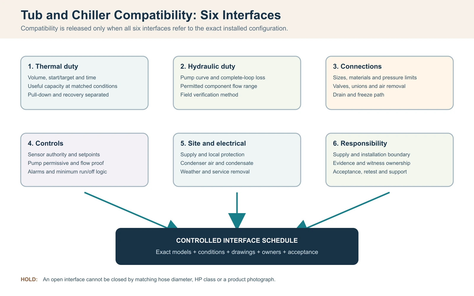
Per questo flusso di abbinamento, considerare una vasca per immersione in acqua fredda e un refrigeratore d'acqua compatibili solo quando sei interfacce si chiudono insieme: carico termico, portata d'acqua e perdita di carico, connessioni fisiche, logica di controllo, condizioni elettriche/di sito e responsabilità del servizio. Abbinare diametri dei tubi o acquistare una classe di potenza superiore non prova la compatibilità. La decisione di rilascio dovrebbe identificare l'esatta vasca, il refrigeratore, la pompa, il filtro, i componenti di trattamento e la revisione dei controlli, non due nomi di categoria.
Inizia con un requisito operativo in una riga: volume d'acqua effettivo, temperature di partenza e target, tempo di raffreddamento consentito, schema di sessioni previsto, intervallo di temperatura ambiente dell'ingresso del condensatore e posizione interna o esterna. Quindi traccia il circuito completo e nomina ogni componente fornito e installato in loco. Una proposta compatibile deve mostrare che la capacità di raffreddamento utile è disponibile alle condizioni dichiarate e che la pompa può muovere l'acqua attraverso l'intera resistenza installata rimanendo entro i limiti di flusso consentiti di ciascun componente.
Registro di rilascio compatibilità vasca e refrigeratore
| Interfaccia | Domanda da chiudere | Evidenza di rilascio |
|---|---|---|
| Termico | La potenza utile può soddisfare i compiti di raffreddamento e recupero alla condizione di progetto? | Dati di capacità legati alla condizione e calcolo limitato |
| Idraulico | Il punto di lavoro della pompa rientra nei limiti di flusso dello scambiatore e del trattamento? | Curva della pompa, base di perdita di pressione e metodo di verifica sul campo |
| Collegamenti | Dimensioni, materiali, valvole, raccordi, scarico e percorsi di sfogo dell'aria sono coordinati? | Disegno approvato del circuito e dei collegamenti |
| Controlli | Quale dispositivo comanda la pompa e il compressore, e cosa interrompe il funzionamento non sicuro? | Sequenza di funzionamento, programma di allarmi e interblocchi |
| Sito/impianto elettrico | Alimentazione elettrica, aria del condensatore, condizioni atmosferiche, drenaggio e accesso per la manutenzione sono fattibili? | Piano del sito e revisione locale qualificata ove richiesto |
| Responsabilità | Chi fornisce, installa, verifica e supporta ciascuna interfaccia? | Matrice di responsabilità e accettazione approvata |
Regola di rilascio: un'interfaccia aperta resta un blocco ingegneristico, anche quando entrambi i prodotti funzionano separatamente. Non utilizzare adattatori non approvati, controlli di bypass o modifiche non approvate della pompa per forzare un adattamento in campo dopo la consegna.
Definisci il circuito idrico completo e il volume operativo reale
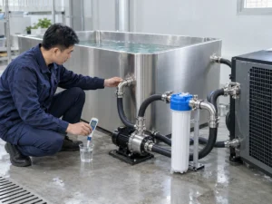
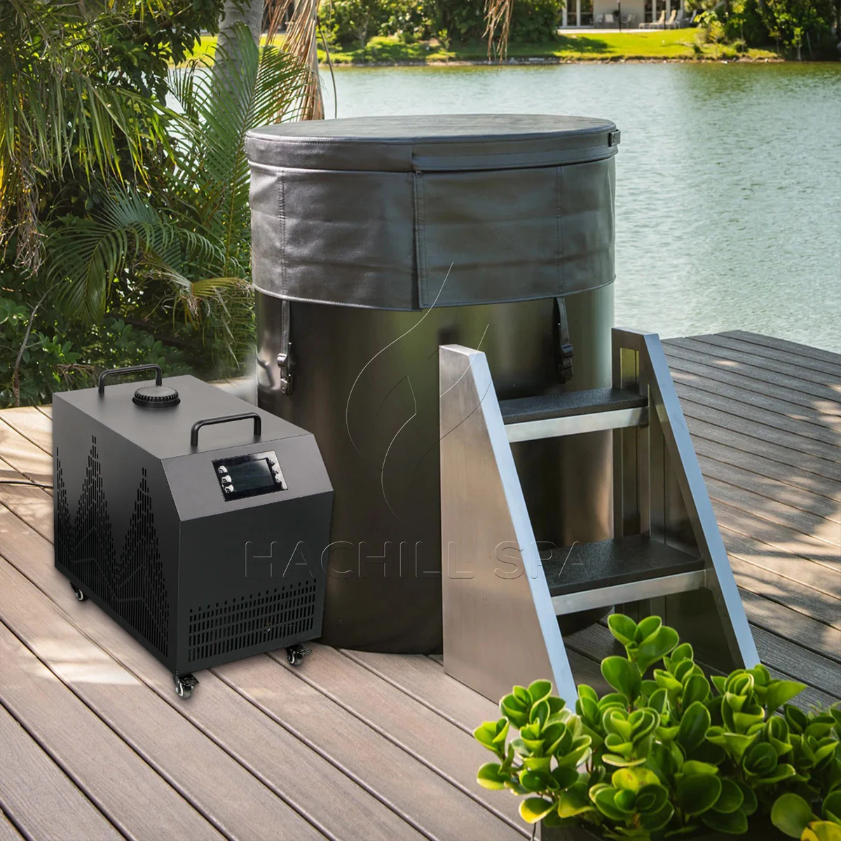
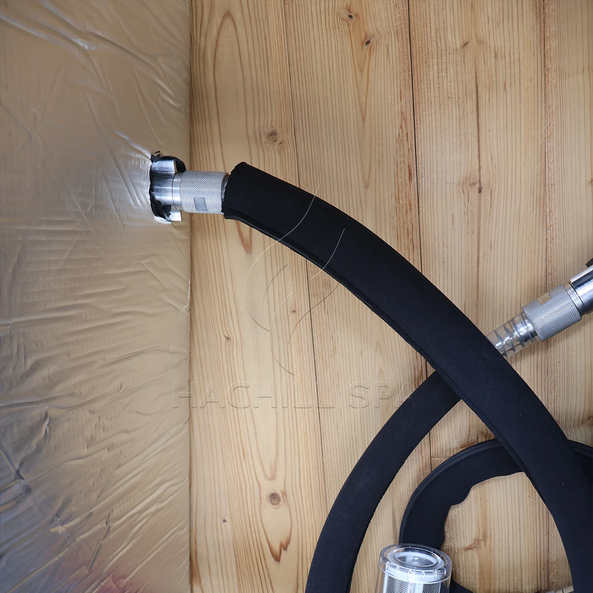
Tracciare il percorso dell'acqua dall'uscita della vasca attraverso filtri a rete, pompa, filtro, componenti di trattamento e scambiatore di calore, quindi di ritorno alla vasca. Includere valvole di intercettazione, valvole di non ritorno, curve, riduzioni, tubi flessibili, risalite verticali ed eventuali bypass. L'ordine dei componenti influisce su priming, rimozione dell'aria, accesso per la manutenzione e su cosa accade quando un filtro si carica. Una fotografia di due attacchi per tubo non mostra il circuito idraulico installato.
Utilizzare il volume d'acqua operativo, non la capacità geometrica massima del serbatoio. Il volume dipende dalla linea di galleggiamento approvata, dallo spostamento interno, dallo spostamento dell'utente e dal fatto che tubazioni esterne o un accumulo aggiungano volume d'acqua materiale. Misurare un riempimento con un contatore adeguato quando i dati del modello approvato non sono disponibili e registrare il metodo di misurazione. La stima dalle dimensioni esterne può sovrastimare o sottostimare la massa termica perché sedute, spessore delle pareti e bordo libero non sono acqua.
Congelare la revisione della configurazione con il circuito. Un distributore può abbinare una vasca di un fornitore con un refrigeratore, una pompa e uno skid di sanificazione separati. Ogni componente può essere singolarmente adatto ma incompatibile come circuito se i materiali di collegamento, le pressioni nominali, le portate richieste o le ipotesi di controllo differiscono. Registrare cosa c'è nella cassa, cosa fornisce l'installatore e quale disegno controlla la disposizione finale.
Verificare il carico termico prima di approvare l'abbinamento del refrigeratore
L'abbinamento vasca/refrigeratore necessita comunque di un gate termico, ma la verifica di compatibilità non deve diventare un secondo flusso completo di dimensionamento. Registrare il volume d'acqua operativo effettivo, le temperature iniziale e target, il tempo di pull-down consentito, l'intervallo di recupero previsto, la temperatura ambiente all'aspirazione del condensatore, lo stato della copertura e il profilo d'uso rappresentativo. L'abbinamento resta aperto finché il refrigeratore selezionato non dispone di evidenza di raffreddamento utile applicabile a tali condizioni.
Per uno screening trasparente del solo circuito idrico, il calore sensibile può essere stimato con Q = m x cp x Delta T. Il manuale di termodinamica del Dipartimento dell’Energia degli Stati Uniti utilizza la stessa relazione del calore sensibile, e la capacità termica dell’acqua liquida varia con la temperatura anziché essere una costante immutabile. Per un volume operativo illustrativo di 400 L, approssimato come 400 kg di acqua, raffreddando da 22 C a 10 C con cp = 4.186 kJ/kg-K fornisce circa 5.58 kWh termici di energia dell'acqua accumulata. Se una potenza utile netta verificata fosse in media di 2.4 kW nelle condizioni rilevanti, il tempo ideale solo acqua sarebbe di circa 2.33 ore.
Questo calcolo è un ponte di screening tra il carico della vasca e l’evidenza del chiller, non una promessa di prestazione HACHILL. Esclude il calore che entra attraverso il vaso, l’acqua esposta, le tubazioni e il locale; il calore della pompa; l’apporto solare; il ciclo di controllo; e le variazioni di capacità disponibile al variare dell’acqua e delle condizioni ambientali. Non aggiungere un margine percentuale generico semplicemente per far sembrare completo il risultato. Trasferire gli apporti termici irrisolti nel flusso di lavoro dedicato al dimensionamento termico o chiuderli con prove controllate sull’intero sistema.
Verifica di compatibilità termica
| Campo | Evidenza minima di corrispondenza | Mantenere aperto l'abbinamento quando |
|---|---|---|
| Volume d'acqua operativa | Linea d'acqua approvata o riempimento misurato, con volume esterno incluso dichiarato | Sono noti solo la capacità nominale della vasca o le dimensioni esterne |
| Duty di abbattimento | Temperature di partenza/obiettivo e tempo consentito | Il preventivo fornisce solo un'affermazione generica “raffredda fino a” |
| Regime di recupero | Evento rappresentativo di utilizzo/riempimento e finestra di recupero richiesta | Un risultato di pull-down notturno viene utilizzato come proxy di uso intenso |
| Stato ambiente/copertura | Condizione della presa del condensatore e stato dichiarato di copertura/apertura | Le prove di capacità sono state prodotte in condizioni non corrispondenti |
| Prove di capacità | Output utile per il modello/configurazione esatti alle condizioni pertinenti | Sono disponibili solo HP, potenza assorbita o un massimo non qualificato |
Verificare la capacità di raffreddamento utile alle stesse condizioni
Cavalli vapore, input del compressore e resa frigorifera utile rispondono a domande diverse. Per la compatibilità, confrontare il duty della vasca con la capacità di raffreddamento dichiarata per la configurazione esatta del chiller alla temperatura dell'acqua, all'ambiente di aspirazione del condensatore, alla portata e all'alimentazione elettrica rilevanti. Un singolo punto con acqua tiepida o ambiente favorevole può essere una prova valida per quel punto ma risultare comunque insufficiente vicino all'obiettivo di progetto.
Mantenete il confine di prova collegato a ogni numero. Chiedete se la capacità dichiarata rappresenta solo l'unità di refrigerazione o il pacchetto completo fornito, e se il comportamento di pompa, ventola, scambiatore di calore e controllo è incluso nel confine dichiarato. Due quotazioni possono mostrare lo stesso valore di capacità pur descrivendo condizioni diverse o parti diverse del sistema.
Un'unità più grande non è automaticamente una scelta migliore. A seconda dell'attrezzatura e del design di controllo, una capacità eccessiva può creare un maggiore fabbisogno elettrico e di aria per il condensatore, spostare il requisito idraulico o produrre cicli brevi quando il carico attivo scende sotto l'intervallo controllabile dell'unità. La selezione corretta deve soddisfare il duty valido più impegnativo rimanendo all'interno dell'esatto inviluppo operativo consentito dal modello.
Evidenze di capacità necessarie per l'abbinamento vasca/chiller
| Campo fornitore | Utilizzalo per | Non sostituire |
|---|---|---|
| Capacità di raffreddamento utile | Tasso di rimozione del calore alle condizioni dichiarate di acqua, ambiente, portata e alimentazione | Classe HP o input del compressore |
| Risultato del pull-down | Evidenza solo quando volume, inizio/target, ambiente, copertura e configurazione sono dichiarati | Un'affermazione non qualificata su ore necessarie per raggiungere la temperatura |
| Inviluppo operativo | Limiti consentiti di acqua/ambiente/flusso per la revisione ordinata | Un punto di prova di catalogo |
| Ingresso elettrico | Analisi del carico e dell'efficienza del sito entro un confine definito | Potenza frigorifera |
| Comportamento in controllo/carico minimo | Se l'unità selezionata può rimanere stabile al diminuire del carico | L'ipotesi che una maggiore capacità sia sempre più sicura |
Trovare il punto di funzionamento della pompa lungo l'intero circuito
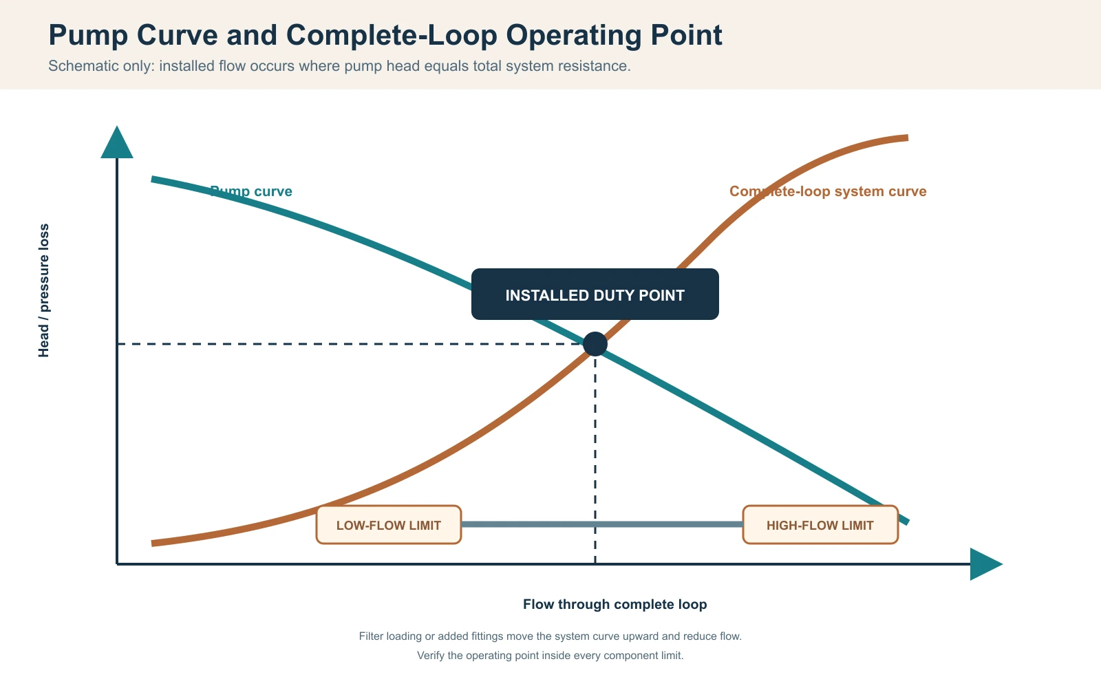
Per una pompa a velocità fissa senza un dispositivo attivo di controllo della portata, il punto di funzionamento installato è dove la curva della pompa interseca la curva di resistenza del sistema; la Guida combinata di Hydraulic Institute’s su curve di pompa e sistema documenta questa relazione. Il controllo a velocità variabile o una valvola di controllo attiva possono spostare o mantenere il punto operativo, ma la capacità della pompa e la resistenza del sistema completo devono comunque essere riconciliate. La portata massima della pompa, comunemente dichiarata a prevalenza minima o nulla, non può essere trattata come portata installata. Costruire la resistenza da tubo diritto, tubo flessibile, raccordi, valvole, filtro o cestello filtrante, dispositivi di trattamento e scambiatore di calore del chiller alla portata di progetto. Includere la condizione di servizio: un filtro pulito può superare la messa in servizio mentre un filtro carico sposta poi il sistema fuori dall’intervallo di portata consentito del chiller.
Utilizzare i dati di perdita di carico del produttore per i componenti, quando disponibili. Per le tubazioni, un progettista qualificato può calcolare le perdite per attrito e localizzate utilizzando diametro, lunghezza, materiale e raccordi approvati. La prevalenza statica in un circuito chiuso a ricircolo non viene gestita come un sollevamento aperto, ma l'adescamento e l'aria intrappolata sono comunque importanti. Non aggiungere né omettere termini di elevazione senza definire la configurazione effettiva.
Un controllo del bilancio termico lato acqua può supportare il collaudo: Qdot = portata massica x cp x Delta T. Per una portata verificata illustrativa di 30 L/min, la portata massica dell'acqua è circa 0.5 kg/s. Se una differenza stabile e calibrata tra ingresso e uscita è 1.0 K, il trasferimento lato acqua è approssimativamente 0.5 x 4.186 x 1.0 = 2.09 kW. Questo risultato è sensibile all'accuratezza della portata, alla polarizzazione dei sensori, alla miscelazione, all'allineamento temporale e all'accumulo transitorio; non è valido quando le letture vengono effettuate in tempi o posizioni diverse.
Registrazione del punto di funzionamento idraulico
| Articolo | Evidenza di progetto | Evidenza di campo |
|---|---|---|
| Pompa | Curva per modello esatto, velocità e frequenza | Modalità operativa e indicazione di servizio verificata |
| Tubazioni e tubi flessibili | Diametro interno, lunghezza, materiale e percorso | Revisione installata e controllo di pieghe/restrizioni |
| Raccordi e valvole | Quantità, tipo e posizione | Registrazione della posizione delle valvole come installate |
| Filtro/trattamento | Perdita di carico a filtro pulito e in servizio | Indicazione di condizione e pressione dove prevista |
| Scambiatore di calore | Intervallo di portata consentito e perdita di carico | Metodo di flusso, temperatura di ingresso/uscita e allarmi |
| Incertezza | Campo di misura dello strumento e precisione richiesta | Identità, stato di verifica, posizione e marca temporale |
Coordinare limiti di flusso, adescamento, rimozione dell'aria e scarico antigelo
Sia una portata bassa sia una portata eccessiva possono invalidare una corrispondenza. Una portata bassa può ridurre il trasferimento di calore lato acqua e può attivare la protezione di flusso o antigelo; una portata superiore al limite approvato di un componente può superare i valori nominali di scambiatore di calore, filtro o collegamento e può aumentare perdita di carico, rumore o usura legata alla velocità a seconda del design. Confermare l'intervallo consentito per ogni componente in serie, quindi selezionare un punto operativo all'interno dell'intervallo applicabile più stretto con margine per il normale caricamento del filtro.
Posizionare la pompa e le valvole in modo che il circuito possa essere riempito, sfiatato e adescato secondo il metodo approvato. Un problema frequente all'avviamento si verifica quando la pompa contiene aria: sembra attiva ma non stabilisce la circolazione, quindi il refrigeratore segnala bassa portata o la pompa funziona a secco. Controllare il livello dell'acqua, la posizione delle valvole, le perdite in aspirazione, i punti alti intrappolati e le fasi di adescamento del manuale. Non bypassare mai un flussostato per forzare il funzionamento del compressore.
Scenario di progettazione: dimensioni raccordi corrispondenti, ma allarmi ripetuti di portata ridotta
Problema osservato: La vasca e il chiller utilizzano entrambi la stessa dimensione nominale del raccordo, ma il sistema installato scatta dopo l'aggiunta del filtro.
Causa probabile: La selezione ha confrontato il diametro del raccordo ma ha trascurato la lunghezza del tubo, i gomiti, la perdita di carico del filtro e la curva della pompa.
Come verificare: Bloccare il circuito installato, verificare le condizioni di valvole e filtro, calcolare la resistenza e misurare la portata con un metodo approvato.
Prevenzione o percorso correttivo: Selezionare la pompa in base al punto di lavoro dell'intero circuito e mantenere un margine di servizio senza superare i limiti dei componenti.
Le installazioni all'aperto o non riscaldate richiedono una strategia di protezione dal gelo definita. Identificare ogni punto basso, volume intrappolato e componente che richiede scarico o circolazione protetta. Un raccordo di scarico sulla vasca non svuota automaticamente il chiller, lo scambiatore di calore, la pompa o il tubo esterno. Utilizzare le istruzioni del modello e la progettazione professionale specifica per il clima; i danni da gelo non possono essere prevenuti con una procedura generica da blog.
Abbinare sensori, setpoint, abilitazioni pompa e logica di allarme
Decidere quale sensore controlla il sistema e dove misura. Un sensore all'interno del chiller può rilevare acqua diversa dalla massa mista della vasca, soprattutto a bassa portata o subito dopo l'ingresso di un utente. Registrare la posizione del sensore, le ipotesi di miscelazione, la risoluzione visualizzata e qualsiasi procedura di offset. Non spostare un sensore dopo l'accettazione senza rivedere la base di prova.
La sequenza di funzionamento deve indicare quando la pompa di circolazione si avvia, cosa prova il flusso, quando il compressore è abilitato, come viene applicato il differenziale del setpoint e cosa succede dopo un allarme o un'interruzione di corrente. Se il controller della vasca e il chiller esterno comandano entrambi la temperatura, setpoint contrastanti possono creare cicli instabili. Scegliere un'unica autorità di controllo o documentare una sequenza coordinata.
La corrispondenza elettrica include tensione, frequenza, fase, corrente nominale, comportamento all'avvio, requisiti di sezionamento e protezione per la destinazione. La sezione finale dei conduttori, la protezione da sovracorrente, il sezionamento, la messa a terra/equipotenzialità e qualsiasi requisito GFCI o RCD devono seguire i dati dell'attrezzatura ordinata, le istruzioni del produttore e le regole elettriche locali applicabili, con i lavori regolamentati completati da professionisti locali qualificati. Per i luoghi di lavoro negli Stati Uniti, OSHA 1910.333 definisce pratiche di lavoro relative alla sicurezza e limita i lavori sotto tensione a persone qualificate. Un adattatore di spina non corregge tensione o frequenza incompatibili.
Scenario di progettazione: capacità corretta, temperatura instabile
Problema osservato: L'acqua raggiunge il target, ma il compressore si avvia e si ferma frequentemente e le temperature visualizzate non coincidono.
Causa probabile: Due controller utilizzano setpoint diversi, il sensore vede acqua di ritorno poco miscelata, oppure la logica minima di funzionamento/arresto non è stata coordinata.
Come verificare: Registrare entrambi i display, lo stato della pompa, lo stato del compressore, le posizioni dei sensori e i setpoint di controllo su una sola linea temporale.
Prevenzione o percorso correttivo: Approvare un'unica sequenza di funzionamento, l'autorità del sensore e la risposta agli allarmi prima della produzione o del cablaggio in sito.
Verificare aria del condensatore, condizioni meteorologiche, condensa e spazio di servizio
Un chiller raffreddato ad aria rigetta nell'aria circostante il calore della vasca più l'input del compressore; Guida ASHRAE’s sui condensatori descrive lo smaltimento del calore del condensatore come il carico dell'evaporatore più l'input energetico del compressore. L'aspirazione necessita di aria entro l'intervallo ambientale approvato, e lo scarico caldo non deve ricircolare nell'aspirazione. Un'unità collocata all'interno di un armadio stretto può avere spazio visivo sufficiente per i tubi ma un'area libera insufficiente per il flusso d'aria, causando una riduzione della potenza o la protezione contro l'alta pressione.
Misurare la temperatura ambiente alla presa del condensatore durante un test di prestazione, non a un termostato remoto della stanza. Registrare l'esposizione solare, scarichi vicini, pareti, schermi e altre apparecchiature che possono modificare le condizioni di aspirazione. Per le aree impiantistiche interne, coordinare la ventilazione o la dissipazione del calore con il team dell'edificio. Per il posizionamento all'aperto, confermare l'idoneità dell'involucro, l'esposizione a pioggia e detriti, il drenaggio, gli effetti del vento e qualsiasi limite operativo a bassa temperatura dal manuale esatto.
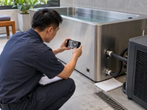
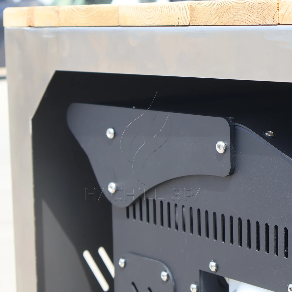
Tubi e componenti freddi possono produrre condensa. Instradarla in modo che l'acqua non possa creare rischio di scivolamento, danneggiare le finiture o raggiungere apparecchiature elettriche. Mantenere l'accesso a filtri, valvole, pannelli e qualsiasi componente che debba essere rimosso. Un pannello di servizio visibile in un'immagine del prodotto non dimostra che possa aprirsi dopo che l'unità è stata integrata in un mobile.
Raccogliere dati sincronizzati prima di attribuire una causa alla prestazione
Raccogliere una registrazione sincronizzata per l'intero sistema. Identificare la vasca esatta, il chiller, la pompa, il filtro e le revisioni di controllo; il volume operativo effettivo; l'identità e la posizione del sensore; il metodo di verifica del flusso; la temperatura ambiente alla presa del condensatore; le temperature dell'acqua in ingresso, uscita e massa mista; lo stato di pompa/compressore; la condizione del filtro; lo stato del coperchio; il confine elettrico; timestamp e deviazioni. Letture non sincronizzate non possono supportare un calcolo affidabile della capacità lato acqua.
Registro dati di commissioning di vasca e chiller
| Punto di registrazione | Dati termici/ambientali | Dati idraulici/di controllo | Evidenza di configurazione |
|---|---|---|---|
| Prima del riempimento | Temperatura dell'acqua di sorgente e ambiente di progetto | Stato di valvole, scarichi e filtri | Disegni approvati e identità dei componenti |
| Avvia | Temperature miste del volume, ingresso/uscita e aspirazione del condensatore | Metodo di flusso verificato, modalità pompa e setpoint | Volume d'acqua, stato di alimentazione e copertura |
| Intervalli fissi | Stessi sensori e timestamp | Stato di pompa/compressore/ventilatore e allarmi | Aperture, solare o altre deviazioni |
| Recupero sessione | Volume misto prima/dopo e ambiente | Stato di controllo e continuità di circolazione | Numero utenti, tempi e perdita d'acqua |
| Endpoint | Volume misto finale e ambiente di aspirazione | Flusso stabile e transizione di controllo | Riferimenti a testimonianze, strumentazione ed eccezioni |
Classificare una carenza prima di assegnare le responsabilità. Una causa di tipo termico può comportare condizioni di capacità non corrispondenti o guadagno termico omesso. Una causa di tipo idraulico può comportare portata ridotta, filtro carico o presenza di aria. Una causa di tipo controllo può comportare posizione del sensore, interblocchi o cicli. Una causa di tipo sito può comportare aria del condensatore ricircolata, carico solare o alimentazione elettrica errata. Una causa di tipo dati può comportare portata non verificata, deriva del sensore o timestamp mancanti.
Interrompere il test e richiedere un servizio qualificato in caso di ripetuti interventi di protezione elettrica o di pressione, cablaggio danneggiato, indicazione di perdita di refrigerante o olio, fumo, surriscaldamento, pompa in funzione senza acqua, congelamento incontrollato o perdite alle interfacce elettriche. Gli operatori possono verificare le condizioni visibili consentite dal manuale; non devono aprire gli involucri elettrici o di refrigerazione né bypassare le protezioni.
Assegnare la responsabilità dell'interfaccia e valutare le prove
Matrice delle responsabilità dell'interfaccia tra vasca e chiller
| Interfaccia | Fornitore di attrezzature | Acquirente/gestore | Installatore/professionista locale | Evidenze di chiusura |
|---|---|---|---|---|
| Base del servizio | Esaminare la fattibilità e dichiarare gli input aperti | Modello di utilizzo proprio e servizio target | Revisione delle implicazioni del sito | Brief operativo approvato |
| Selezione termica | Fornire evidenze del modello legate alle condizioni | Approvare tempi e condizioni richiesti | Verificare il confine installato | Registro di selezione e base di accettazione |
| Circuito idraulico | Fornire limiti dei componenti e collegamenti | Approvare l'ambito fornitura/sito | Progettare/installare/verificare il circuito di sito | Disegno del circuito e registro di flusso |
| Controlli | Fornire sequenza, allarmi e interfacce | Approvare l'autorità operativa | Completare l'integrazione di sito consentita | Programma di controllo e test funzionale |
| Elettrico/sito | Fornire dati esatti del modello e spazi liberi | Fornire input di destinazione e impianto | Progettazione qualificata e approvazione | Registri di rilascio del sito |
| Messa in servizio | Supporto ai controlli specifici del prodotto | Fornire operatore e testimone | Verificare l'installazione e i lavori regolamentati | Risultato firmato, deviazioni e stato della ripetizione del test |
Classificare le prove in base all'applicabilità. Un test con testimone specifico dell'ordine a condizioni concordate è il più forte per l'accettazione contrattuale. Prove indipendenti o accreditate possono supportare la conformità o le prestazioni solo entro il modello e l'ambito dichiarati. I dati del produttore specifici del modello con metodo e condizioni supportano la selezione ingegneristica. I calcoli trasparenti supportano lo screening. Brochure generiche, etichette HP e fotografie supportano solo la scoperta.
Utilizzare punti di fermo prima di ordinare penetrazioni nel sito, rilasciare la produzione, spedire il sistema e aprirlo agli utenti. Un riferimento a uno standard o a una certificazione descrive un ambito; non prova che il modello, la tensione o la configurazione HACHILL ordinati possiedano tale approvazione. Mantenere aperta qualsiasi prova di destinazione richiesta fino a quando il revisore responsabile non conferma l'esatta applicabilità.
Avviare secondo un confine scritto, quindi ritestare la causa
Scrivere l'accettazione prima del test sul campo. Indicare configurazione, volume d'acqua, condizioni di partenza e obiettivo, tempo consentito o punto di capacità lato acqua, banda ambiente di aspirazione del condensatore, intervallo di portata e metodo di verifica, stato del filtro, stato di copertura e solare, confine elettrico, posizioni dei sensori, stato degli strumenti, modalità di controllo, punto finale e testimoni. Predefinire cosa rende non valida una prova e quale deviazione può essere accettata.
Registro di accettazione della compatibilità e delle controversie
| Controversia osservata | Prove richieste | Disposizione |
|---|---|---|
| Il raffreddamento è lento | Volume, temperature, ambiente, portata, controlli e guadagni di calore corrispondenti | Separare le cause di selezione, idrauliche, di controllo, di sito e di dati |
| La portata è contestata | Curva della pompa, resistenza installata, stato del filtro e metodo di verifica | Correggere il circuito o il metodo; non dedurre la portata dall'aspetto |
| I display non concordano | Identità del sensore, posizione, miscelazione e stato di verifica | Correggere la base di misurazione e ripetere il test |
| Il refrigeratore scatta | Cronologia allarmi, flusso d'aria, portata, alimentazione e limiti manuali | Interrompere il lavoro non sicuro; diagnosi qualificata prima del ripristino/ripetizione del test |
| L'ambito è incompleto | Programma delle interfacce approvato, disegno e registro di imballaggio | Sospendere l'installazione o l'accettazione fino alla chiusura della responsabilità |
| Condizioni modificate | Registro delle deviazioni e tolleranza pre-concordata | Invalidare o classificare il lotto prima di giudicare le prestazioni |
Una ripetizione del test dovrebbe modificare solo la causa identificata e preservare le altre condizioni per quanto possibile. Se il flusso non era verificato, correggere il metodo e ripetere; se l'aria del condensatore ricircolava, correggere la condizione del sito e ripetere; se i sensori erano distorti, verificarli o sostituirli e ripetere. Registrare chi autorizza la ripetizione e chi ne sostiene il costo per ciascuna categoria di causa.
Scenario ingegneristico: il refrigeratore risulta sottodimensionato solo dopo l'installazione
Problema osservato: I dati del fornitore suggerivano una resa adeguata, ma il raffreddamento in campo è lento.
Causa probabile: Il test in sito utilizza aspirazione del condensatore più calda, flusso inferiore e una vasca scoperta, mentre la base di selezione utilizzava condizioni diverse.
Come verificare: Riconciliare ogni input di accettazione e classificare le deviazioni termiche, idrauliche, di controllo, di sito e dei dati.
Prevenzione o percorso correttivo: Congelare le prove legate alla condizione e il confine di messa in servizio prima del rilascio dell'ordine, quindi ripetere il test solo dopo che la causa è stata controllata.
Emettere un programma di interfaccia controllato e il record finale Go/No-Go
Il registro finale di compatibilità dovrebbe adattarsi a un programma controllato: modelli e revisioni esatti, volume d'acqua operativo, carichi termici, prove di capacità e condizioni, punto di funzionamento della pompa, limiti di flusso dei componenti, dimensioni e materiali dei collegamenti, disegno del circuito, sequenza di controllo, alimentazione elettrica, confine dell'aria del condensatore, metodo di congelamento e scarico, spazi di manutenzione, responsabili e test di accettazione. Ogni voce aperta deve avere un responsabile, una data di scadenza e un effetto sul rilascio.
Per una richiesta di preventivo, inviare volume d'acqua, temperature iniziale e target, tempi di raffreddamento e recupero, utenti e programma, posizione interna/esterna, intervallo di temperatura ambiente, percorso tubazioni, ambito di filtrazione e trattamento, alimentazione disponibile, integrazione del controllo, mercato di destinazione e prove richieste. Chiedere ai fornitori di restituire inclusioni, esclusioni e ipotesi nello stesso programma in modo che i preventivi possano essere confrontati senza colmare le lacune con linguaggio commerciale.
- Congelare il volume esatto della vasca e la revisione completa del circuito dell'acqua.
- Separare i carichi di raffreddamento, mantenimento e recupero della sessione.
- Abbinare la potenza frigorifera utile alle condizioni rilevanti di acqua, ambiente, flusso e alimentazione.
- Tracciare o documentare il punto di funzionamento della pompa rispetto alla resistenza totale del circuito.
- Confermare gli intervalli di flusso dei componenti, il priming, la rimozione dell'aria e lo scarico antigelo.
- Approvare l'autorità del sensore, i permessi della pompa, gli allarmi e la logica anti-ciclo breve.
- Assegnare ogni interfaccia fornita e installata in sito.
- Scrivere le regole di accettazione, deviazione, arresto, ripetizione del test e controversia prima della spedizione.
HACHILL può esaminare un abbinamento di famiglia di prodotti o modello quando l'acquirente fornisce questi input. Qualsiasi valore di modello non verificato, ambito di certificazione o ipotesi sul sito dovrebbe rimanere aperto fino a quando non è supportato da dati specifici dell'ordine; la revisione non sostituisce il lavoro elettrico, strutturale, di salute pubblica o di refrigerazione autorizzato.
Domande frequenti
Che refrigeratore mi serve per una vasca per immersione fredda?
Non esiste una risposta affidabile basata solo sul volume della vasca. Per questa pagina di abbinamento, gli input richiesti sono volume operativo, temperature iniziale e target, finestre di pull-down e recupero, ambiente di aspirazione del condensatore, programma utente, stato di copertura/isolamento e idraulica. Usare la guida dedicata al dimensionamento termico per calcolare il duty di progetto, poi tornare qui per chiudere le interfacce vasca/chiller con dati di modello legati alle condizioni.
La potenza in cavalli del refrigeratore è uguale alla capacità di raffreddamento?
N. La potenza in cavalli può descrivere un compressore o una classe di dimensioni commerciale, mentre la capacità di raffreddamento utile dipende dall'intero sistema di refrigerazione e dalle condizioni di prova. Confrontare la capacità di rimozione del calore alle temperature dell'acqua e ambiente indicate.
Perché una vasca fredda può raffreddarsi più lentamente all'aperto?
Aria più calda in ingresso al condensatore, apporto termico solare, ricircolo dell’aria di scarico, tubazioni esposte e isolamento o controllo della copertura deboli possono aumentare il carico del sistema o ridurre la potenza disponibile del chiller. Le prestazioni effettive dipendono anche da flusso, condizione del filtro e inviluppo operativo dell’unità esatta.
La pompa di circolazione può essere selezionata in base alla portata massima?
No. La portata massima o a prevalenza zero non mostra il punto di lavoro installato. Tubazioni, raccordi, filtro e scambiatore di calore creano perdite di carico, mentre il dislivello statico deve essere trattato in base all'effettiva configurazione del circuito aperto/chiuso. Utilizzare la curva esatta della pompa, la resistenza dell’intero sistema e l’intervallo di portata approvato del chiller.
Cosa dovrebbe includere un registro di messa in servizio del refrigeratore?
Registrare la revisione esatta di vasca/chiller/pompa, il volume d'acqua operativo, le temperature sincronizzate dell'acqua e dell'aspirazione del condensatore, il metodo di portata verificato, lo stato del filtro, le posizioni dei sensori, i setpoint di controllo, lo stato della pompa/compressore, il confine dell'alimentazione elettrica, i timestamp, gli allarmi e eventuali deviazioni. Confrontare la prova solo con la base di accettazione concordata in anticipo.
Risorse HACHILL correlate
Categoria di prodotto: vasca per immersione fredda
Usare la categoria di prodotto per passare dai requisiti di interfaccia di sistema alla famiglia di prodotti cold plunge appropriata.
I chiller per vasche di immersione fredda funzionano a 24/7?
Utilizzare la guida sul ciclo di lavoro quando la domanda aperta è se il raffreddatore deve funzionare continuamente o può ciclare attorno a un carico operativo definito.
Soluzioni commerciali per l'immersione fredda
Utilizzare la pagina delle soluzioni commerciali quando il tipo di acquirente, la sede e la portata del progetto sono ora più importanti dell'interfaccia vasca-raffreddatore stessa.
Richiedi un preventivo per il progetto
Utilizzare il percorso RFQ quando il programma delle interfacce ha abbastanza input chiusi per una revisione del fornitore.
Base di riferimento
- Dipartimento dell'Energia degli Stati Uniti, DOE-HDBK-1012/1-92: Termodinamica, trasmissione del calore e flusso dei fluidi – Supporta le relazioni di calore sensibile e trasferimento di calore utilizzate per i calcoli di screening; non è uno standard di prestazione per bagni freddi.
- NIST Chemistry WebBook: acqua – Dati termofisici di riferimento che mostrano che la capacità termica dell'acqua liquida dipende dalla temperatura; i calcoli di progetto devono dichiarare la base di proprietà utilizzata.
- Hydraulic Institute: curve combinate di pompa & sistema – Base del punto di funzionamento pompa/sistema; curve esatte della pompa, modalità di controllo e resistenza installata governano comunque il punto di lavoro reale.
- ASHRAE Handbook, Capitolo 39: Condensatori – Base di reiezione del calore del condensatore di refrigerazione; i manuali esatti delle apparecchiature regolano i limiti ambientali, i requisiti di flusso d'aria e le distanze di servizio.
- OSHA 1910.333 – Riferimento statunitense sulle pratiche di lavoro elettrico correlate alla sicurezza sul lavoro, ove applicabile; non sostituisce le regole di progettazione elettrica del paese di destinazione né il manuale dell'apparecchiatura.
Confine tecnico e di sicurezza per Come abbinare una vasca di immersione fredda a un chiller: I manuali di prodotto, i disegni approvati, i requisiti locali applicabili edilizi, elettrici, di salute pubblica e di accessibilità, e le maestranze qualificate hanno priorità rispetto alle indicazioni generiche del web. Questo articolo non dichiara certificazioni o prestazioni garantite in sito.
Trasforma l'interfaccia in un brief di progetto
Inviare a HACHILL la vasca o la shortlist, il volume operativo, il carico di temperatura, l'intervallo ambientale, la disposizione del circuito, l'ambito del trattamento, l'alimentazione, la destinazione e i record richiesti. Il team può rivedere un abbinamento mantenendo aperti i campi non supportati.