دليل هندسة أحواض الغطس البارد
توافق فني بين الحوض والمبرد لصالح المشترين ومهندسي المنتجات وفنيي التركيب والموزعين.
إجابة مباشرة: يتم مطابقة حوض الغطس البارد مع المبرد من خلال إغلاق ستة واجهات للنظام المركّب الفعلي: الحمل الحراري، ونقطة التشغيل الهيدروليكية، والتوصيلات الفيزيائية، ومنطق التحكم، والظروف الكهربائية وظروف الموقع، ومسؤولية التركيب والقبول. ابدأ بحجم الماء التشغيلي الفعلي، ودرجات حرارة البداية والهدف، ونوافذ التبريد السريع والاستعادة المطلوبة، ودرجة حرارة الهواء المحيط بمدخل المكثف، ودورة الماء الكاملة. ثم تحقق من سعة التبريد المرتبطة بالظروف ومن نقطة تشغيل المضخة التي تُبقي كل مكوّن في السلسلة ضمن نطاق التدفق المسموح به.
حجم الوصلة وحجم الحوض وقدرة المبرد بالحصان حقول فرز مفيدة، لكن أياً منها لا يثبت التوافق بمفرده. سجل الإفراج الموثّق يحدد الحوض والمبرد والمضخة ومكوّنات الترشيح/المعالجة وأدوات التحكم وافتراضات الموقع بدقة، ثم يسجّل ما تم التحقق منه وما لا يزال مفتوحاً وما قد يوقف الإفراج.
نطاق الصفحة: تتناول هذه المقالة مطابقة الواجهة بين الحوض والمبرد. وتستخدم فقط القدر الكافي من منطق الحمل الحراري والسعة لاختبار تلك الواجهة. أما حسابات حمل التبريد الكاملة للمشروع فتنتمي إلى دليل هندسة الحرارة وأحجام المبردات لأحواض الغطس البارد; ؛ ومقارنة القدرة بالحصان بسعة التبريد المفيدة تنتمي إلى مقارنة القدرة الحصانية لمبرد حوض الغطس البارد بقدرة التبريد. يجب أن تأتي توصيلات الطراز المحدد وحدود التشغيل والتصنيفات من البيانات المعتمدة للتهيئة المطلوبة.
في هذه الصفحة
- أغلق ست واجهات قبل اعتبار الحوض والمبرد متوافقين
- حدد دورة المياه الكاملة وحجم التشغيل الفعلي
- تحقق من الحمل الحراري قبل اعتماد مطابقة المبرد
- تحقق من سعة التبريد المفيدة عند الظروف نفسها
- ابحث عن نقطة تشغيل المضخة عبر الدورة الكاملة
- تنسيق حدود التدفق، والتهيئة، وإزالة الهواء، وتصريف الحماية من التجمد
- مطابقة المستشعرات، ونقاط الضبط، وأذونات المضخة، ومنطق الإنذار
- التحقق من هواء المكثف، والطقس، والمكثفات، ومساحة الخدمة
- جمع بيانات متزامنة قبل تحديد سبب الأداء
- تحديد مسؤولية الواجهة وتقييم الأدلة
- الاختبار وفقًا لحدود مكتوبة، ثم إعادة اختبار السبب
- إصدار جدول واجهة مُتحكم به وسجل قبول/رفض نهائي
أغلق ست واجهات قبل اعتبار الحوض والمبرد متوافقين
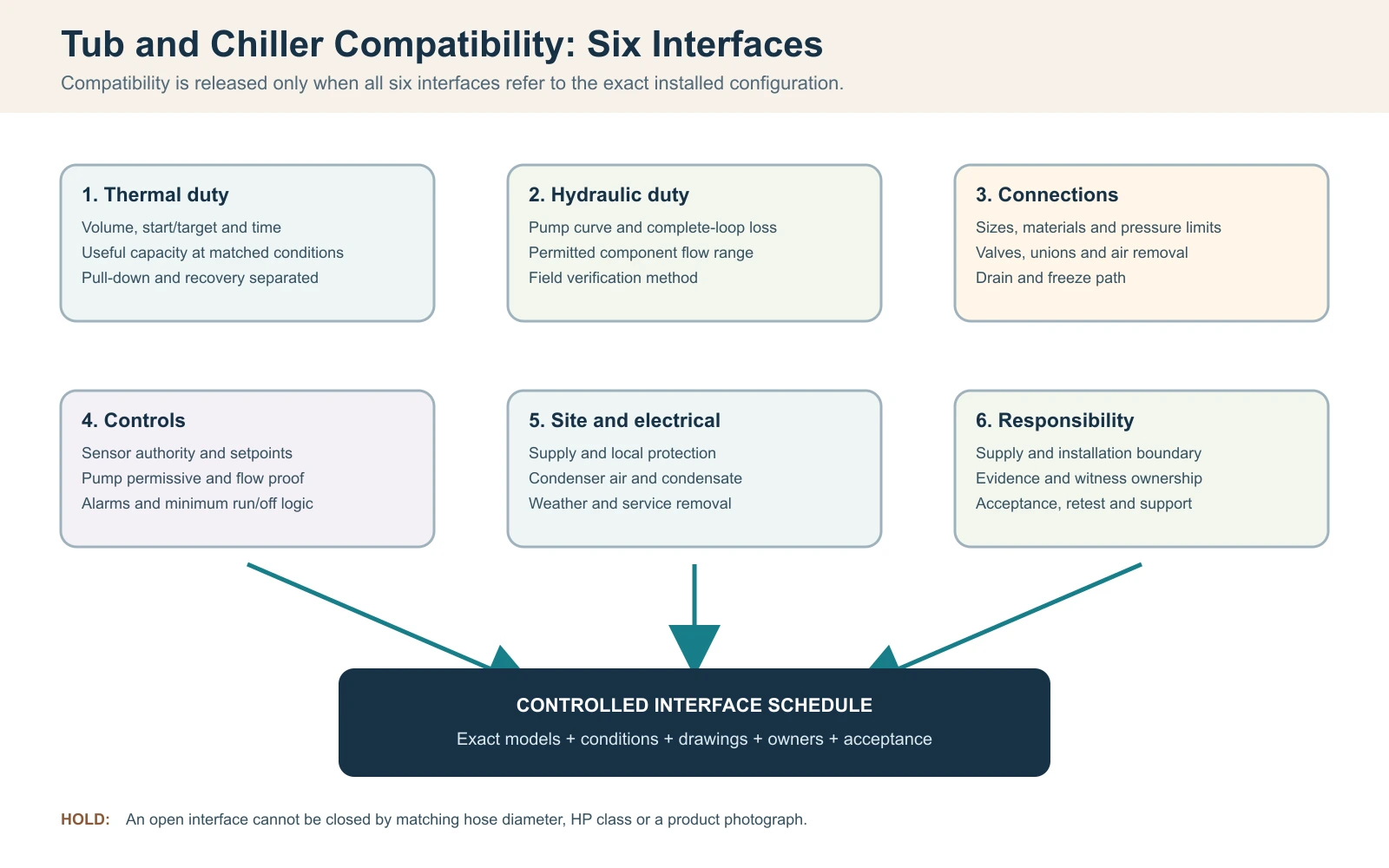
في سير المطابقة هذا، يُعتبر حوض الغطس البارد والمبرد متوافقين فقط عندما تُغلق ست واجهات معاً: الحمل الحراري، وتدفق الماء وفقد الضغط، والتوصيلات الفيزيائية، ومنطق التحكم، والظروف الكهربائية وظروف الموقع، ومسؤولية الخدمة. مطابقة أقطار الخراطيم أو شراء فئة قدرة حصانية أكبر لا يثبت التوافق. يجب أن يحدد قرار الإفراج الحوض والمبرد والمضخة والمرشح ومكوّنات المعالجة ومراجعة التحكم بدقة، لا مجرد اسمين فئويين.
ابدأ بمتطلب تشغيلي من سطر واحد: حجم المياه الفعلي، ودرجات حرارة البداية والهدف، ووقت التبريد المسموح به، ونمط الجلسة المتوقع، ونطاق درجة حرارة الهواء المحيط لمدخل المكثف، والموقع الداخلي أو الخارجي. ثم ارسم الحلقة الكاملة وسمِّ كل مكون يتم توفيره أو تركيبه في الموقع. يجب أن يُظهر الاقتراح المتوافق أن سعة التبريد المفيدة متاحة في الظروف المعلنة وأن المضخة قادرة على تحريك المياه عبر المقاومة الكاملة المثبتة مع البقاء ضمن نطاق التدفق المسموح لكل مكون.
سجل إصدار توافق الحوض والمبرد
| الواجهة | سؤال يجب إغلاقه | دليل الإصدار |
|---|---|---|
| حراري | هل يمكن أن يفي الإخراج المفيد بواجبات السحب والاسترداد عند شرط التصميم؟ | بيانات السعة المرتبطة بالشرط والحساب المحدود |
| هيدروليكي | هل تقع نقطة تشغيل المضخة ضمن حدود تدفق المبادل والمعالجة؟ | منحنى المضخة، أساس فقدان الضغط وطريقة التحقق الميداني |
| التوصيلات | هل الأحجام والمواد والصمامات والوصلات ومسارات التصريف وإزالة الهواء منسقة؟ | رسم معتمد للحلقة والتوصيل |
| أدوات التحكم | أي جهاز يتحكم في المضخة والضاغط، وما الذي يوقف التشغيل غير الآمن؟ | تسلسل التشغيل وجدول الإنذار والتعشيق |
| الموقع/الكهرباء | هل الطاقة، وهواء المكثف، والطقس، والصرف، وإزالة الخدمة قابلة للتطبيق؟ | مخطط الموقع ومراجعة محلية مؤهلة عند الحاجة |
| المسؤولية | من يقوم بتوريد وتركيب والتحقق ودعم كل واجهة؟ | مصفوفة المسؤولية والقبول المعتمدة |
قاعدة الإصدار: تبقى الواجهة المفتوحة بمثابة تعليق هندسي، حتى عندما يعمل المنتجان بشكل منفصل. لا تستخدم محولات غير معتمدة أو أدوات تحكم تجاوزية أو تغييرات مضخة غير معتمدة لفرض ملاءمة ميدانية بعد التسليم.
حدد دورة المياه الكاملة وحجم التشغيل الفعلي
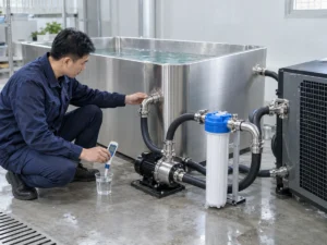
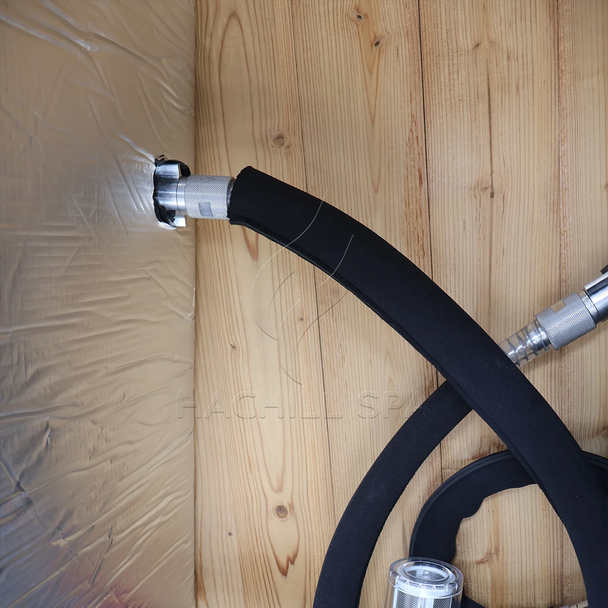
حدد مسار المياه من مخرج الحوض عبر المصافي والمضخة والفلتر ومكونات المعالجة والمبادل الحراري، ثم العودة إلى الحوض. قم بتضمين صمامات العزل وصمامات الفحص والكوع والمخفضات والخرطوم المرن والارتفاعات الرأسية وأي مسار جانبي. يؤثر ترتيب المكونات على عملية التعبئة وإزالة الهواء وسهولة الصيانة وما يحدث عندما يتسخ الفلتر. لا تُظهر صورة طرفي خرطوم الدائرة الهيدروليكية المركبة.
استخدم حجم المياه التشغيلي، وليس السعة الهندسية القصوى للحوض. يعتمد الحجم على خط المياه المعتمد والإزاحة الداخلية وإزاحة المستخدم وما إذا كانت الأنابيب الخارجية أو خزان إضافي يضيف حجم مياه فعليًا. قم بقياس التعبئة بعداد مناسب عندما لا تتوفر بيانات النموذج المعتمدة، وسجل طريقة القياس. قد يؤدي التخمين من الأبعاد الخارجية إلى المبالغة في تقدير الكتلة الحرارية أو التقليل منها لأن المقاعد وسماكة الجدران والارتفاع الحر ليست مياهًا.
ثبّت مراجعة التكوين مع الدائرة. قد يقوم الموزع بدمج حوض من مورد واحد مع مبرد ومضخة ووحدة تعقيم منفصلة. يمكن أن يكون كل مكون مناسبًا بشكل فردي ولكنه غير متوافق كدائرة إذا اختلفت مواد التوصيل أو تصنيفات الضغط أو التدفقات المطلوبة أو افتراضات التحكم. سجل ما هو موجود في الصندوق وما يوفره المثبت وأي رسم يتحكم في الترتيب النهائي.
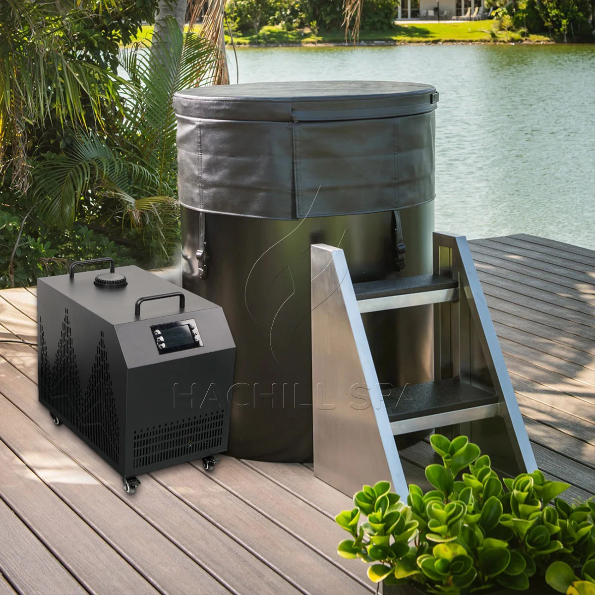
تحقق من الحمل الحراري قبل اعتماد مطابقة المبرد
لا تزال مطابقة الحوض/المبرد بحاجة إلى بوابة حرارية، لكن فحص التوافق يجب ألا يتحول إلى سير عمل ثانٍ كامل لتحديد الأحجام. سجّل حجم الماء التشغيلي الفعلي، ودرجات الحرارة الابتدائية والهدف، وزمن التبريد السريع المسموح، وفترة الاستعادة المتوقعة، ودرجة حرارة الهواء المحيط بمدخل المكثف، وحالة الغطاء، وجدول المستخدم التمثيلي. تبقى المطابقة مفتوحة حتى يتوفر للمبرد المختار دليل تبريد مفيد ينطبق على تلك الظروف.
لفرز شفاف للماء فقط، يمكن تقدير الحرارة المحسوسة باستخدام Q = m × cp × ΔT. يستخدم دليل الديناميكا الحرارية الصادر عن وزارة الطاقة الأمريكية نفس علاقة الحرارة المعقولة، وتتفاوت السعة الحرارية للماء السائل مع درجة الحرارة بدلاً من كونها ثابتاً واحداً غير متغير. لحجم تشغيلي توضيحي قدره 400 L، يُقدَّر بنحو 400 kg من الماء، عند التبريد من 22 C إلى 10 C مع cp = 4.186 kJ/kg-K يعطي حوالي 5.58 كيلوواط ساعي حراري من طاقة الماء المخزنة. إذا بلغ متوسط صافي الإنتاج المفيد المُتحقق منه 2.4 kW عبر الظروف المعنية، فإن الزمن المثالي للماء فقط سيكون حوالي 2.33 ساعة.
هذا الحساب جسر فرز بين واجب الحوض وأدلة المبرد، وليس وعداً بأداء من HACHILL. وهو يستبعد الحرارة الداخلة عبر الوعاء والماء المكشوف والأنابيب والغرفة؛ وحرارة المضخة؛ والكسب الشمسي؛ ودورات التحكم؛ والتغيرات في السعة المتاحة مع تغير الماء والظروف المحيطة. لا تُضِف هامشاً نسبياً عاماً لمجرد أن تبدو النتيجة مكتملة. انقل مكاسب الحرارة غير المحسومة إلى سير عمل التحجيم الحراري المخصص أو أغلقها باختبار كامل للنظام تحت السيطرة.
بوابة التوافق الحراري
| الحقل | الحد الأدنى من أدلة المطابقة | أبقِ الاقتران مفتوحاً عندما |
|---|---|---|
| حجم الماء التشغيلي | خط الماء المعتمد أو التعبئة المقاسة، مع ذكر الحجم الخارجي المشمول | لا يُعرف سوى السعة الاسمية للوعاء أو الأبعاد الخارجية |
| واجب التخفيض السريع لدرجة الحرارة | درجات حرارة البداية/الهدف والزمن المسموح | يعطي عرض السعر فقط ادعاءً عاماً بأنه “يبرد إلى” |
| واجب الاستعادة | حدث استخدام/إعادة تعبئة نموذجي ونافذة الاستعادة المطلوبة | يُستخدم نتيجة خفض الحرارة خلال الليل كبديل عن الاستخدام المكثف |
| حالة المحيط/الغطاء | حالة مدخل المكثف وحالة الغطاء/الفتح المعلنة | أُنتجت بيانات السعة في ظروف غير متطابقة |
| بيانات السعة | الخرج المفيد للطراز/التكوين المحدد في الظروف ذات الصلة | يتوفر فقط HP أو قدرة الإدخال أو قيمة قصوى غير مؤهلة |
تحقق من سعة التبريد المفيدة عند الظروف نفسها
تجيب القدرة بالحصان وقدرة إدخال الضاغط والخرج المفيد للتبريد عن أسئلة مختلفة. لأغراض التوافق، قارن حمل الحوض بقدرة التبريد المعلنة لتكوين المبرد المحدد عند درجة حرارة الماء ذات الصلة، وحالة المحيط عند مدخل المكثف، والتدفق، والتغذية الكهربائية. قد تكون نقطة واحدة لماء دافئ أو محيط مواتٍ دليلاً صالحاً لتلك النقطة، لكنها تظل غير كافية قرب هدف المشروع.
أبقِ حدود الاختبار مرتبطة بكل رقم. اسأل ما إذا كانت السعة المعلنة تمثل وحدة التبريد وحدها أم الحزمة الكاملة الموردة، وما إذا كانت المضخة والمروحة والمبادل الحراري وسلوك التحكم مشمولة في الحدود المعلنة. قد يعرض عرضان سعر قيمة السعة نفسها بينما يصفان ظروفاً مختلفة أو أجزاءً مختلفة من النظام.
الوحدة الأكبر ليست تلقائياً الخيار الأفضل. حسب تصميم المعدات والتحكم، قد تخلق السعة المفرطة متطلباً أكبر للكهرباء وهواء المكثف، أو تغيّر المتطلب الهيدروليكي، أو تسبب تشغيلاً قصير الدورات عندما ينخفض الحمل الفعلي دون النطاق القابل للتحكم في الوحدة. يجب أن يلبي الاختيار الصحيح أقسى حمل صالح مع البقاء داخل غلاف التشغيل المسموح للطراز المحدد.
بيانات السعة اللازمة لمطابقة الحوض/المبرد
| حقل المورّد | استخدمه لـ | لا تستبدل |
|---|---|---|
| سعة تبريد مفيدة | معدل إزالة الحرارة عند ظروف الماء والمحيط والتدفق والإمداد المُعلنة | مدخل فئة HP أو الضاغط |
| نتيجة خفض الحرارة | دليل فقط عند الإفصاح عن الحجم، وبدء/هدف، والمحيط، والغطاء، والتكوين | ادعاء غير مقيّد بشأن ساعات بلوغ درجة الحرارة |
| نطاق التشغيل | حدود المياه/المحيط/التدفق المسموح بها للإصدار المطلوب | نقطة اختبار كتالوج واحدة |
| الإدخال الكهربائي | تحليل حمل الموقع والكفاءة ضمن نطاق محدّد | خرج التبريد |
| سلوك التحكم/الحمل الأدنى | ما إذا كانت الوحدة المختارة يمكن أن تبقى مستقرة مع انخفاض الحمل | افتراض أن المزيد من السعة أكثر أمانًا دائمًا |
ابحث عن نقطة تشغيل المضخة عبر الدورة الكاملة
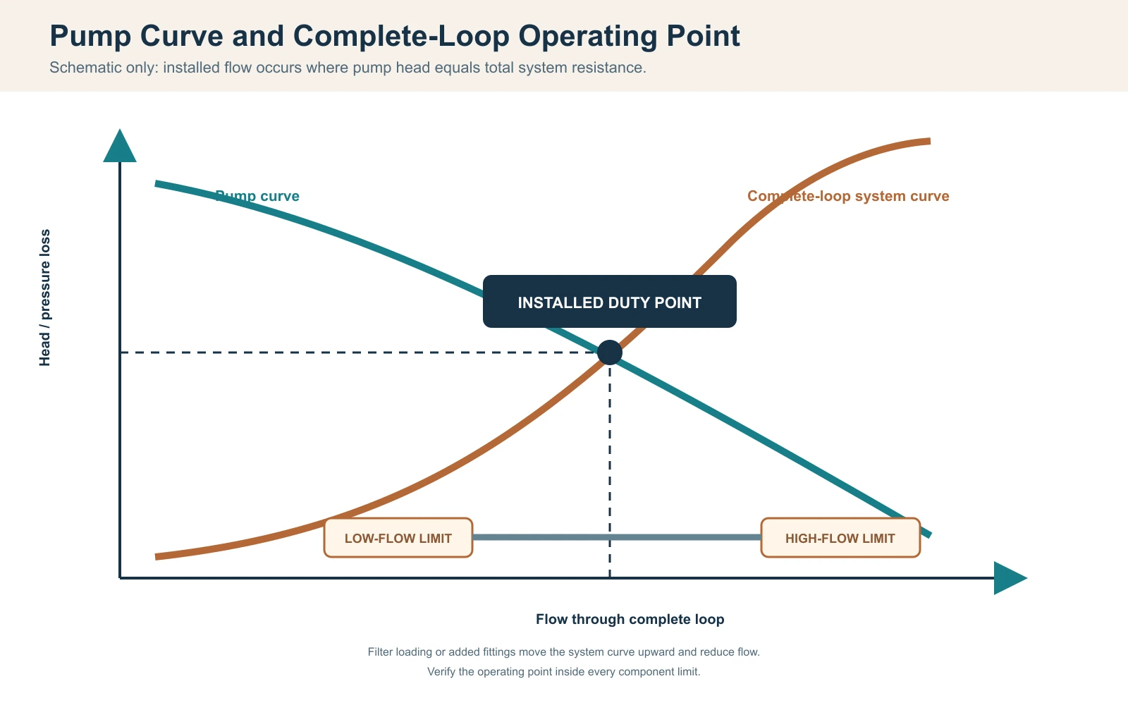
بالنسبة لمضخة ثابتة السرعة دون جهاز تحكم نشط في التدفق، تكون نقطة التشغيل المركّبة حيث يتقاطع منحنى المضخة مع منحنى مقاومة النظام؛ و إرشادات معهد Hydraulic Institute بشأن منحنى المضخة ومنحنى النظام المجمّعين توثّق هذه العلاقة. يمكن للتحكم متغير السرعة أو صمام تحكم نشط أن يزيح نقطة التشغيل أو يثبّتها، لكن لا يزال يجب التوفيق بين قدرة المضخة ومقاومة المنظومة الكاملة. لا يمكن اعتبار التدفق الأقصى للمضخة، الذي يُذكر عادة عند ضغط ارتفاع ضئيل أو معدوم، تدفقاً مركّباً. ابنِ المقاومة من الأنبوب المستقيم، والخرطوم، والوصلات، والصمامات، والمرشّح أو المصفاة، وأجهزة المعالجة، والمبادل الحراري للمبرّد عند تدفق التصميم. أدرج حالة الخدمة: قد يجتاز المرشّح النظيف التشغيل التجريبي، بينما ينقل مرشّح محمّل لاحقاً النظام خارج نطاق التدفق المسموح به لـ chiller’s.
استخدم بيانات فقدان الضغط من الشركة المصنعة للمكونات عند توفرها. بالنسبة لشبكات الأنابيب، يمكن لمصمم مؤهل حساب خسائر الاحتكاك والخسائر الثانوية باستخدام القطر المعتمد والطول والمادة والتجهيزات. لا يتم التعامل مع الارتفاع الاستاتيكي في حلقة دوران مغلقة بنفس طريقة الرفع المفتوح، ولكن التهيئة والهواء المحتبس ما زالا مهمين. لا تضف أو تحذف حدود الارتفاع دون تحديد الترتيب الفعلي.
يمكن أن يدعم فحص توازن الحرارة على جانب الماء عملية التشغيل: Qdot = معدل التدفق الكتلي × cp × Delta T. بالنسبة لتدفق موثق توضيحي قدره 30 L/min، يكون معدل التدفق الكتلي للماء حوالي 0.5 kg/ثانية. إذا كان الفرق المستقر والمعاير بين الدخول والخروج هو 1.0 كلفن، فإن الانتقال الحراري على جانب الماء يكون تقريبًا 0.5 x 4.186 x 1.0 = 2.09 kW. هذه النتيجة حساسة لدقة التدفق، وانحياز المستشعر، والخلط، ومحاذاة الوقت، والتخزين العابر؛ ولا تكون صالحة عندما تؤخذ القراءات في أوقات أو مواقع مختلفة.
سجل نقطة التشغيل الهيدروليكية
| العنصر | أدلة التصميم | أدلة ميدانية |
|---|---|---|
| المضخة | منحنى الطراز المحدد والسرعة والتردد | وضع التشغيل ومؤشر الحمل الموثق |
| الأنابيب والخراطيم | القطر الداخلي والطول والمادة والتوجيه | المراجعة المثبتة وفحص الانثناء/الانسداد |
| التجهيزات والصمامات | العدد والنوع والموضع | سجل مواضع الصمامات كما تم تركيبها |
| الفلترة/المعالجة | فقدان الضغط النظيف والخدمي | بيان الحالة والضغط عند توفرهما |
| المبادل الحراري | نطاق التدفق المسموح وفقدان الضغط | طريقة التدفق، درجة حرارة المدخل/المخرج والإنذارات |
| عدم اليقين | مدى الجهاز والدقة المطلوبة | الهوية، حالة التحقق، الموقع والطابع الزمني |
تنسيق حدود التدفق، والتهيئة، وإزالة الهواء، وتصريف الحماية من التجمد
يمكن أن يؤدي كل من التدفق المنخفض والتدفق المفرط إلى إبطال المطابقة. قد يقلل التدفق المنخفض نقل الحرارة من جانب الماء وقد يفعّل حماية التدفق أو التجمد؛ كما قد يتجاوز التدفق فوق الحد المعتمد للمكوّن تصنيفات المبادل الحراري أو المرشح أو التوصيلات وقد يزيد انخفاض الضغط أو الضوضاء أو البلى المرتبط بالسرعة حسب التصميم. أكّد النطاق المسموح به لكل مكوّن في السلسلة، ثم اختر نقطة تشغيل داخل أضيق نطاق معمول به مع هامش لتحميل المرشح الطبيعي.
ضع المضخة والصمامات بحيث يمكن ملء الدائرة وتفريغها من الهواء وتجهيزها بالطريقة المعتمدة. تحدث مشكلة شائعة عند بدء التشغيل عندما تحتوي المضخة على هواء: تبدو نشطة لكنها لا تنشئ دورانًا، لذلك يبلغ المبرد عن تدفق منخفض أو تعمل المضخة بدون ماء. تحقق من مستوى الماء، وموضع الصمام، وتسريبات الشفط، والنقاط العالية المحبوسة، وخطوات التجهيز في الدليل. لا تقم أبدًا بتعطيل مفتاح التدفق لإجبار الضاغط على العمل.
سيناريو هندسي: مطابقة أحجام الخراطيم، لكن إنذارات تدفق منخفض متكررة
المشكلة المرصودة: يستخدم كل من الحوض والمبرد نفس حجم الموصل الاسمي، ومع ذلك يتعطل النظام المركب بعد إضافة المرشح.
السبب المحتمل: قارن الاختيار قطر الموصل لكنه أغفل طول الخرطوم، والانحناءات، وفقدان ضغط المرشح، ومنحنى المضخة.
كيفية التحقق: جمّد الدائرة المركبة، وتحقق من حالة الصمام والمرشح، واحسب المقاومة، وقس التدفق بطريقة معتمدة.
مسار الوقاية أو التصحيح: اختر المضخة من نقطة تشغيل الدائرة الكاملة واحتفظ بهامش خدمة دون تجاوز حدود المكونات.
تتطلب التركيبات الخارجية أو غير المدفأة استراتيجية محددة للحماية من التجمد. حدد كل نقطة منخفضة، وكل حجم محبوس، وكل مكون يتطلب تصريفًا أو دورانًا محميًا. لا يؤدي تركيب تصريف على الحوض تلقائيًا إلى تفريغ المبرد أو المبادل الحراري أو المضخة أو الخرطوم الخارجي. استخدم تعليمات الطراز والتصميم المهني الخاص بالمناخ؛ لا يمكن منع أضرار التجمد بإجراء عام من مدونة.
مطابقة المستشعرات، ونقاط الضبط، وأذونات المضخة، ومنطق الإنذار
حدد المستشعر الذي يتحكم في النظام والمكان الذي يقيس فيه. قد يرى المستشعر داخل المبرد ماءً مختلفًا عن مياه الحوض المختلطة الكلية، خاصة عند التدفق المنخفض أو مباشرة بعد دخول مستخدم. سجل موضع المستشعر، وافتراضات الخلط، والدقة المعروضة، وأي إجراء لتصحيح الانحراف. لا تنقل مستشعرًا بعد القبول دون مراجعة أساس الاختبار.
يجب أن يحدد تسلسل التشغيل متى تبدأ مضخة الدوران، وما الذي يثبت التدفق، ومتى يُسمح للضاغط بالعمل، وكيف يتم تطبيق نطاق التوقف لنقطة الضبط، وما يحدث بعد إنذار أو انقطاع التيار. إذا كان كل من وحدة تحكم الحوض والمبرد الخارجي يتحكمان في درجة الحرارة، فإن نقاط الضبط المتعارضة يمكن أن تسبب دورات غير مستقرة. اختر سلطة تحكم واحدة أو وثق تسلسلًا منسقًا.
تشمل المطابقة الكهربائية الجهد والتردد والطور والتيار المقنن وسلوك البدء ومتطلبات الفصل والحماية الخاصة بوجهة التركيب. يجب أن تتبع أحجام الموصلات النهائية والحماية من التيار الزائد والفصل والتأريض/الربط وأي متطلب GFCI أو RCD بيانات المعدات المطلوبة وتعليمات الشركة المصنعة’ وقواعد الكهرباء المحلية المعمول بها، مع إنجاز الأعمال المنظمة بواسطة متخصصين محليين مؤهلين. بالنسبة لبيئات العمل في U.S.، OSHA 1910.333 يحدد ممارسات العمل المتصلة بالسلامة ويقصر العمل على المعدات المكهربة على الأشخاص المؤهلين. لا يصحح محول القابس فرق الجهد أو التردد غير المتوافق.
سيناريو هندسي: سعة صحيحة، درجة حرارة غير مستقرة
المشكلة المرصودة: يصل الماء إلى الهدف، لكن الضاغط يبدأ ويتوقف بشكل متكرر وتختلف درجات الحرارة المعروضة.
السبب المحتمل: يستخدم جهازا التحكم نقاط ضبط مختلفة، أو يرى المستشعر ماء راجعًا غير ممزوج جيدًا، أو لم يتم تنسيق منطق الحد الأدنى للتشغيل/الإيقاف.
كيفية التحقق: سجّل كلا العرضين، وحالة المضخة، وحالة الضاغط، ومواقع المستشعرات، ونقاط ضبط التحكم على خط زمني واحد.
مسار الوقاية أو التصحيح: اعتمد تسلسل تشغيل واحدًا، وسلطة المستشعر، واستجابة الإنذار قبل الإنتاج أو توصيل الأسلاك في الموقع.
التحقق من هواء المكثف، والطقس، والمكثفات، ومساحة الخدمة
المبرد المبرّد بالهواء يطرح حرارة الحوض بالإضافة إلى مدخلات الضاغط إلى الهواء المحيط؛ إرشادات ASHRAE’s بشأن المكثف تصف تصريف حرارة المكثف بأنه حمل المبخر زائد مدخل طاقة الضاغط. يحتاج مدخل الهواء إلى هواء ضمن النطاق المحيط المعتمد، ويجب ألا يعود التصريف الساخن إلى المدخل. قد توفر وحدة موضوعة داخل خزانة ضيقة خلوصًا بصريًا كافيًا للخراطيم لكن مساحة حرة غير كافية لتدفق الهواء، مما يسبب انخفاض الإخراج أو حماية الضغط المرتفع.
قم بقياس درجة الحرارة المحيطة عند سحب المكثف أثناء اختبار الأداء، وليس عند منظم حرارة الغرفة البعيد. سجّل التعرض لأشعة الشمس، والعوادم القريبة، والجدران، والشاشات، والمعدات الأخرى التي يمكن أن تغير ظروف السحب. بالنسبة لمناطق المصنع الداخلية، قم بتنسيق التهوية أو طرد الحرارة مع فريق البناء. بالنسبة للتركيب الخارجي، تأكد من ملاءمة العلبة، والتعرض للمطر والحطام، والصرف، وتأثيرات الرياح، وأي حد تشغيل لدرجة الحرارة المنخفضة من الدليل الدقيق.
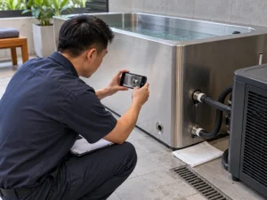
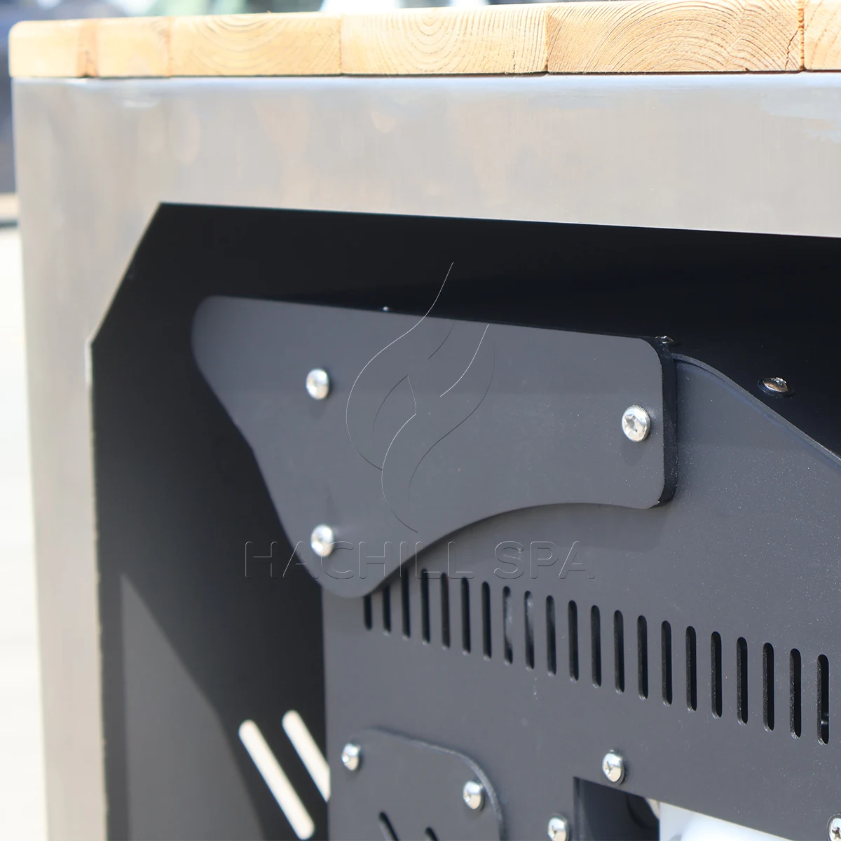
قد تنتج التكثيف عن الأنابيب والمكونات الباردة. وجّهه بحيث لا يمكن للماء أن يسبب خطر انزلاق، أو يتلف التشطيبات، أو يصل إلى المعدات الكهربائية. حافظ على الوصول إلى المرشحات، والصمامات، والألواح، وأي مكون يجب إزالته. لا يثبت لوح الخدمة الظاهر في صورة المنتج أنه يمكن فتحه بعد تركيب الوحدة في النجارة.
جمع بيانات متزامنة قبل تحديد سبب الأداء
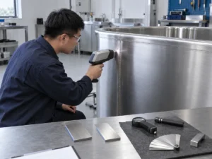
اجمع سجلًا واحدًا متزامنًا للنظام الكامل. حدد الحوض الدقيق، والمبردة، والمضخة، والمرشح، ومراجعات التحكم؛ وحجم التشغيل الفعلي؛ وهوية المستشعر وموضعه؛ وطريقة التحقق من التدفق؛ ودرجة الحرارة المحيطة بسحب المكثف؛ ودرجات حرارة الماء عند المدخل والمخرج والكتلة المختلطة؛ وحالة المضخة/الضاغط؛ وحالة المرشح؛ وحالة الغطاء؛ والحدود الكهربائية؛ والطوابع الزمنية والانحرافات. لا يمكن للقراءات غير المتزامنة أن تدعم حساب سعة موثوقًا لجانب الماء.
سجل بيانات تشغيل الحوض والمبردة
| نقطة التسجيل | بيانات حرارية/بيئية | بيانات هيدروليكية/تحكم | أدلة التكوين |
|---|---|---|---|
| قبل التعبئة | درجة حرارة مصدر المياه والظروف المحيطة التصميمية | حالة الصمام والمصرف والمرشح | المخططات المعتمدة وهويات المكونات |
| البدء | درجات حرارة الكتلة المختلطة والمدخل/المخرج ومدخل المكثف | طريقة التدفق المُتحقق منها ووضع المضخة ونقطة الضبط | حجم المياه وحالة الإمداد والتغطية |
| فترات زمنية ثابتة | نفس المستشعرات والطوابع الزمنية | حالة المضخة/الضاغط/المروحة والإنذارات | الفتحات أو الانحرافات الشمسية أو غيرها |
| استعادة الجلسة | الكتلة المختلطة قبل/بعد والظروف المحيطة | حالة التحكم واستمرارية الدوران | عدد المستخدمين والتوقيت وفقدان المياه |
| نقطة النهاية | الكتلة المختلطة النهائية والظروف المحيطة عند السحب | تدفق مستقر وانتقال التحكم | مراجع الشهود والأدوات والاستثناءات |
صنّف النقص قبل إسناد المسؤولية. قد يتضمن سبب اختيار حراري ظروف سعة غير متطابقة أو حمل حراري محذوف. قد يتضمن سبب هيدروليكي تدفقًا منخفضًا أو مرشحًا محملاً أو هواءً. قد يتضمن سبب تحكم موضع المستشعر أو التعشيقات أو التدوير. قد يتضمن سبب موقع هواء مكثف معاد تدويره أو حمل شمسي أو إمداد كهربائي غير صحيح. قد يتضمن سبب بيانات تدفقًا غير مُتحقق منه أو انحياز مستشعر أو طوابع زمنية مفقودة.
أوقف الاختبار واستخدم خدمة مؤهلة في حالة تكرار حماية كهربائية أو ضغط، أو أسلاك تالفة، أو مؤشر تسرب مبرد أو زيت، أو دخان، أو ارتفاع حرارة، أو مضخة تعمل بدون ماء، أو تجمد غير منضبط، أو تسرب عند الواجهات الكهربائية. يجوز للمشغلين التحقق من الظروف المرئية المسموح بها في الدليل؛ ويجب ألا يفتحوا العبوات الكهربائية أو التبريد أو يتجاوزوا الحماية.
تحديد مسؤولية الواجهة وتقييم الأدلة
مصفوفة مسؤولية واجهة الحوض والمبرد
| الواجهة | مورد المعدات | المشتري/المشغل | المركّب/المحترف المحلي | أدلة الإغلاق |
|---|---|---|---|---|
| أساس الواجب | مراجعة الجدوى والإعلان عن المدخلات المفتوحة | نمط الاستخدام الخاص والواجب المستهدف | مراجعة آثار الموقع | موجز تشغيل معتمد |
| الاختيار الحراري | تقديم أدلة نموذج مرتبطة بالحالة | اعتماد الأوقات والشروط المطلوبة | التحقق من الحدود المركبة | سجل الاختيار وأساس القبول |
| الحلقة الهيدروليكية | توفير حدود المكونات والتوصيلات | اعتماد نطاق التوريد/الموقع | تصميم/تركيب/التحقق من دائرة الموقع | رسم الحلقة وسجل التدفق |
| أدوات التحكم | توفير التسلسل والإنذارات والواجهات | اعتماد سلطة التشغيل | تكامل الموقع الكامل المسموح به | التحكم في الجدول الزمني والاختبار الوظيفي |
| الكهرباء/الموقع | توفير بيانات الطراز الدقيقة والخلوصات | توفير مدخلات الوجهة والمنشأة | التصميم والموافقة المؤهلان | سجلات إصدار الموقع |
| التشغيل التجريبي | دعم الفحوصات الخاصة بالمنتج | توفير المشغل والشاهد | التحقق من التركيب والأعمال المنظمة | النتيجة الموقعة والانحرافات وحالة إعادة الاختبار |
دليل الدرجة حسب قابلية التطبيق. الاختبار المشهود الخاص بالطلب في الظروف المتفق عليها هو الأقوى للقبول التعاقدي. يمكن للأدلة المستقلة أو المعتمدة أن تدعم الامتثال أو الأداء فقط ضمن النموذج والنطاق المذكورين. البيانات المصنعية الخاصة بالنموذج مع الطريقة والظروف تدعم الاختيار الهندسي. الحسابات الشفافة تدعم الفحص الأولي. الكتيبات العامة وملصقات HP والصور تدعم الاكتشاف فقط.
استخدم نقاط التوقف قبل طلب الاختراقات في الموقع، والإفراج عن الإنتاج، وشحن النظام، وفتحه للمستخدمين. يشير مرجع المعيار أو الشهادة إلى نطاق؛ ولا يثبت أن نموذج HACHILL المطلوب أو الجهد أو التكوين يحمل هذا الاعتماد. أبقِ أي دليل وجهة مطلوب مفتوحًا حتى يؤكد المراجع المسؤول قابلية التطبيق الدقيقة.
الاختبار وفقًا لحدود مكتوبة، ثم إعادة اختبار السبب
اكتب القبول قبل الاختبار الميداني. حدد التكوين، وحجم الماء، وظروف البداية والهدف، والوقت المسموح أو نقطة سعة الجانب المائي، ونطاق درجة حرارة المحيط عند مدخل المكثف، ونطاق التدفق وطريقة التحقق، وحالة الفلتر، والغطاء وحالة الطاقة الشمسية، والحدود الكهربائية، ومواقع المستشعرات، وحالة الأجهزة، ووضع التحكم، ونقطة النهاية والشهود. حدد مسبقًا ما يجعل التشغيل غير صالح وما يمكن قبوله من انحراف.
سجل قبول التوافق والنزاعات
| نزاع ملاحظ | الأدلة المطلوبة | القرار |
|---|---|---|
| التبريد البطيء | الحجم المطابق ودرجات الحرارة والمحيط والتدفق ووسائل التحكم والمكاسب الحرارية | أسباب منفصلة للاختيار والهيدروليكا والتحكم والموقع والبيانات |
| التدفق محل نزاع | منحنى المضخة والمقاومة المركبة وحالة الفلتر وطريقة التحقق | صحح الدائرة أو الطريقة؛ لا تستنتج التدفق من المظهر |
| الشاشات تتعارض | هوية المستشعر وموضعه وخلطه وحالة التحقق | صحح أساس القياس وأعد الاختبار |
| انقطاع تشغيل المبرد | سجل الإنذارات وتدفق الهواء والتدفق والإمداد والحدود اليدوية | أوقف العمل غير الآمن؛ تشخيص مؤهل قبل إعادة الضبط/إعادة الاختبار |
| النطاق غير مكتمل | جدول الواجهات المعتمد والرسم وسجل التعبئة | أوقف التركيب أو القبول حتى إغلاق المسؤولية |
| تغيرت الظروف | سجل الانحرافات والتفاوت المتفق عليه مسبقًا | أبطل الدفعة أو حدد مصيرها قبل الحكم على الأداء |
يجب أن يغير الاختبار المعاد السبب المحدد فقط ويحافظ على الظروف الأخرى قدر الإمكان عمليًا. إذا كان التدفق غير مُتحقق منه، صحح الطريقة وأعد الاختبار؛ وإذا كان هواء المكثف يُعاد تدويره، صحح حالة الموقع وأعد الاختبار؛ وإذا كانت المستشعرات منحازة، تحقق منها أو استبدلها وأعد الاختبار. سجل من يأذن بالاختبار المعاد ومن يتحمل تكلفته تحت كل فئة سبب.
سيناريو هندسي: يبدو المبرد أصغر من المطلوب فقط بعد التركيب
المشكلة المرصودة: بيانات المورد أشارت إلى خرج كافٍ، لكن التبريد الميداني بطيء.
السبب المحتمل: يستخدم اختبار الموقع مدخل مكثف أكثر سخونة، وتدفقًا أقل، وحوضًا غير مغطى بينما استخدم أساس الاختيار ظروفًا مختلفة.
كيفية التحقق: طابق كل مدخلات القبول وصنف الانحرافات الحرارية والهيدروليكية والتحكمية والموقعية والبيانية.
مسار الوقاية أو التصحيح: جمّد الأدلة المرتبطة بالظروف وحدود التشغيل قبل إصدار أمر الشراء، ثم أعد الاختبار فقط بعد السيطرة على السبب.
إصدار جدول واجهة مُتحكم به وسجل قبول/رفض نهائي
يجب أن يتناسب سجل التوافق النهائي مع جدول زمني مُحكم: الموديلات والمراجعات الدقيقة، حجم الماء التشغيلي، الأحمال الحرارية، أدلة السعة والظروف، نقطة تشغيل المضخة، حدود تدفق المكونات، أحجام الوصلات والمواد، رسم الدائرة، تسلسل التحكم، التغذية الكهربائية، حدود هواء المكثف، طريقة التجميد والتصريف، خلوصات الخدمة، مالكي المسؤولية واختبارات القبول. كل بند مفتوح يحتاج إلى مالك وتاريخ استحقاق وتأثير على الإصدار.
لطلب عرض سعر، أرسل حجم الماء، درجات الحرارة الأولية والمستهدفة، أوقات التبريد والاستعادة، المستخدمين والجدول الزمني، الموقع الداخلي/الخارجي، نطاق درجة الحرارة المحيطة، مسار الأنابيب، نطاق الترشيح والمعالجة، الطاقة المتاحة، تكامل التحكم، السوق المستهدف والأدلة المطلوبة. اطلب من الموردين إعادة التضمينات والاستثناءات والافتراضات في نفس الجدول حتى يمكن مقارنة العروض دون ملء الفجوات بلغة تسويقية.
- جمّد حجم الحوض الدقيق ومراجعة دائرة الماء الكاملة.
- افصل بين واجبات التبريد السريع والتثبيت واستعادة الجلسة.
- طابق خرج التبريد المفيد عند ظروف الماء والبيئة والتدفق والتغذية ذات الصلة.
- ارسم أو وثق نقطة تشغيل المضخة مقابل مقاومة الدائرة الكاملة.
- أكد نطاقات تدفق المكونات، والتعبئة الأولية، وإزالة الهواء، وتصريف التجميد.
- اعتمد سلطة المستشعر، وسماحيات المضخة، والإنذارات، ومنطق منع الدورات القصيرة.
- حدد كل واجهة موردة ومثبتة في الموقع.
- اكتب قواعد القبول والانحراف والإيقاف والاختبار المعاد والنزاع قبل الشحن.
يمكن لـ HACHILL مراجعة توافق عائلة منتجات أو نموذج معين عندما يقدم المشتري هذه المدخلات. أي قيمة نموذج غير موثقة، أو نطاق شهادة، أو افتراض موقع يجب أن يظل مفتوحًا حتى تدعمه بيانات خاصة بالطلب؛ ولا تحل المراجعة محل الأعمال المرخصة في المجالات الكهربائية أو الإنشائية أو الصحة العامة أو التبريد.
الأسئلة الشائعة
ما حجم المبرد الذي أحتاجه لحوض الغطس البارد؟
لا توجد إجابة موثوقة من حجم الحوض وحده. بالنسبة لصفحة المطابقة هذه، المدخلات المطلوبة هي حجم التشغيل، ودرجات حرارة البداية والهدف، ونوافذ التبريد والتعافي، ودرجة الحرارة المحيطة عند مدخل المكثف، وجدول المستخدم، وحالة الغطاء/العزل، والهيدروليكا. استخدم دليل التحجيم الحراري المخصص لحساب حمل المشروع، ثم عد إلى هنا لإغلاق واجهات الحوض/المبرد ببيانات طراز مرتبطة بالحالة.
هل قوة حصان المبرد هي نفسها سعة التبريد؟
ملاحظة: قد يشير الحصان إلى الضاغط أو فئة الحجم التسويقية، بينما تعتمد سعة التبريد الفعلية على نظام التبريد الكامل وظروف الاختبار. قارن قدرة إزالة الحرارة عند درجات حرارة المياه والمحيط المحددة.
لماذا قد يبرد حوض الغمر البارد بشكل أبطأ في الخارج؟
يمكن أن يؤدي ارتفاع حرارة هواء سحب المكثف، واكتساب الحرارة الشمسية، وإعادة تدوير هواء التصريف، والأنابيب المكشوفة، وضعف العزل أو التحكم بالغطاء إلى زيادة حمل النظام أو تقليل خرج المبرّد المتاح. يعتمد الأداء الفعلي أيضًا على التدفق، وحالة الفلتر، ونطاق تشغيل الوحدة’ بالضبط.
هل يمكن اختيار مضخة التدوير بناءً على أقصى معدل تدفق؟
لا. لا يُظهر التدفق الأقصى أو عند ارتفاع ضغط صفري نقطة التشغيل المركّبة. فالأنابيب والتجهيزات والمرشح والمبادل الحراري تخلق فقدان ضغط، كما يجب معالجة الارتفاع الساكن وفقًا لترتيب الدائرة الفعلي المفتوح/المغلق. استخدم منحنى المضخة الدقيق، ومقاومة النظام الكامل، ونطاق التدفق المعتمد للمبرد’.
ما الذي يجب أن يتضمنه سجل تشغيل المبرد؟
سجّل مراجعة الحوض/التشيلر/المضخة الدقيقة، وحجم المياه التشغيلي، ودرجات حرارة المياه وسحب المكثف المتزامنة، وطريقة التدفق المتحقق منها، وحالة الفلتر، ومواقع المستشعرات، ونقاط ضبط التحكم، وحالة المضخة/الضاغط، وحدود الإمداد الكهربائي، والطوابع الزمنية، والإنذارات، وأي انحرافات. قارن التشغيل فقط بأساس القبول المتفق عليه مسبقًا.
موارد HACHILL ذات الصلة
فئة منتج الغطس البارد
استخدم فئة المنتج للانتقال من متطلبات واجهة النظام إلى عائلة منتجات الغمر البارد المناسبة.
هل تعمل مبردات الغطس البارد بنظام 24/7؟
استخدم دليل دورة التشغيل عندما يكون السؤال المفتوح هو ما إذا كان يجب أن يعمل المبرّد باستمرار أو يمكنه الدوران حول حمل تشغيل محدد.
حلول الغمر البارد التجارية
استخدم صفحة الحل التجاري عندما يصبح نوع المشتري والمكان ونطاق المشروع أكثر أهمية من واجهة الحوض إلى المبرّد نفسها.
اطلب عرض سعر للمشروع
استخدم مسار RFQ بمجرد أن يصبح لدى جدول الواجهات مدخلات مغلقة كافية لمراجعة المورّد.
أساس المرجعية
- وزارة الطاقة الأمريكية، DOE-HDBK-1012/1-92: الديناميكا الحرارية، وانتقال الحرارة، وتدفق الموائع – يدعم علاقات الحرارة المحسوسة وانتقال الحرارة المستخدمة في حسابات الفرز؛ وليس معيار أداء لحوض الغمر البارد.
- NIST Chemistry WebBook: الماء – بيانات مرجعية للخصائص الحرارية الفيزيائية تُظهر أن السعة الحرارية للماء السائل تعتمد على درجة الحرارة؛ وينبغي أن تعلن حسابات المشروع الأساس الخاصية الذي تستخدمه.
- معهد الهيدروليك: منحنيات المضخة & النظام المُجمّعة – أساس نقطة تشغيل المضخة/النظام؛ لا تزال منحنيات المضخة الدقيقة، ووضع التحكم، والمقاومة المركّبة تحكم نقطة التشغيل الفعلية.
- دليل ASHRAE، الفصل 39: المكثفات – أساس طرد حرارة مكثف التبريد؛ وتحدد أدلة المعدات الدقيقة حدود البيئة المحيطة ومتطلبات تدفق الهواء وخلوصات الخدمة.
- OSHA 1910.333 – مرجع لممارسات العمل الكهربائي المتعلقة بسلامة مكان العمل في U.S. حيث ينطبق؛ وهو لا يحل محل قواعد التصميم الكهربائي في الوجهة أو دليل المعدات.
الحدود الفنية والسلامة لكيفية مطابقة حوض الغطس البارد مع المبرد: تكون أدلة المنتج، والرسومات المعتمدة، ومتطلبات البناء والكهرباء والصحة العامة وإمكانية الوصول المحلية المعمول بها، والمهن المؤهلة، ذات أولوية على الإرشاد العام عبر الويب. لا تدّعي هذه المقالة الحصول على اعتماد أو ضمان أداء الموقع.
حوّل الواجهة إلى موجز مشروع
أرسل إلى HACHILL الحوض أو القائمة المختصرة، وحجم التشغيل، ومهمة درجة الحرارة، ونطاق الحرارة المحيطة، وترتيب الحلقة، ونطاق المعالجة، والطاقة، والوجهة، والسجلات المطلوبة. يمكن للفريق مراجعة الاقتران مع إبقاء الحقول غير المدعومة مفتوحة.