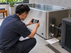
Direct answer: Move a commercial upright cold plunge into exact-model comparison only after five gates are sufficiently closed: intended users can use the planned access arrangement, the complete station can fit, the commercial operating duty is defined, major building/plant/delivery interfaces have responsible owners, and the evidence is specific enough for model-level selection. If a decision-critical input is still open, keep the format on HOLD rather than treating the uncertainty as a minor scoring penalty.
The question is not simply whether an upright tub looks compact or appears suitable for a gym, spa or recovery facility. The useful buying question is:
Can the Upright format work for this project’s users, complete station, operating duty and site interfaces with evidence specific enough to justify model-level selection?
PROCEED — the critical format gates are sufficiently closed for exact-model review.
HOLD — decision-critical evidence is missing.
REDESIGN — Upright may remain viable after a project condition changes.
EVALUATE ANOTHER FORMAT — a critical Upright-specific condition cannot reasonably be satisfied.
This guide owns that format-level go/no-go decision. Detailed ergonomics, facility-type scoring, installed-footprint calculations, water-care procedures, chiller matching and exact model specifications remain separate decisions. For the broader system-level purchase decision across cold-plunge formats, use the Cold Plunge Tub Buying Guide for Businesses and Product Buyers.
Decide Whether Upright Belongs on the Commercial Shortlist
An Upright format is worth considering when its more vertical user relationship and floor arrangement fit the project. Those characteristics justify screening the format; they do not prove that Upright has already qualified.
What Upright Can Change at Format Level
Compared with a more horizontal cold-plunge format, Upright can change several early planning questions:
- how users approach and enter the vessel;
- how much horizontal vessel length is required;
- where steps, supports or other access components sit;
- how the station relates to nearby fixed construction;
- how external cooling equipment and service space interact with the tub;
- how the unit must be delivered into and eventually removed from the site.
These differences help determine what must be verified before a buyer starts comparing exact models.
They do not establish that Upright is automatically smaller, easier to use or better for commercial operation.
A narrow wellness room illustrates the distinction. Limited floor length may make Upright attractive, but the format has not qualified if the proposed access arrangement is unresolved, the external cooling equipment has no workable location or service access consumes space the concept drawing ignored.
The first decision is therefore not:
“Which Upright model should we buy?”
It is:
“Does Upright deserve to stay on the shortlist?”
What an Upright Label Does Not Prove
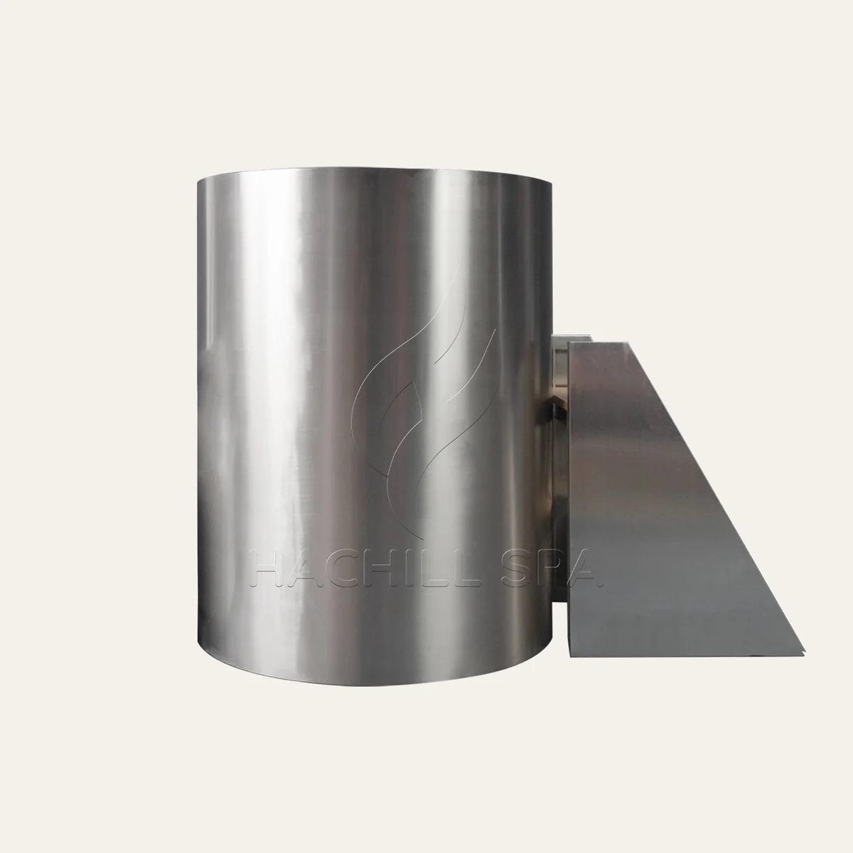
Upright is a body format, not a complete specification.
Different Upright models can have different external geometry, materials, access components and project interfaces. Exact product facts belong to the current model record rather than being generalized across the format.
Commercial suitability also cannot be inferred from the label alone.
| Qualification question | If supported | If open or failed |
|---|---|---|
| Can intended users use the proposed access arrangement? | Continue | HOLD or reconsider format |
| Can the complete station fit? | Continue | HOLD / redesign |
| Is the commercial operating duty defined? | Continue | HOLD |
| Are major site and system interfaces assigned and sufficiently verified? | Continue | HOLD |
| Is the evidence specific enough for model selection? | Proceed to model review | Keep qualification open |
This is deliberately different from a conventional feature scorecard. A decision-critical failure should not be averaged against appearance, material preference or a compact vessel footprint.
Apply the User and Access Gate Before Comparing Models
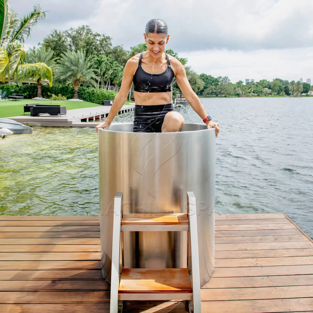
User and access viability is a format gate, not a cosmetic preference.
Before exact-model comparison, the project needs enough evidence to answer:
Can the intended users use the planned Upright access arrangement within the facility’s defined operating boundary?
At buying-guide level, record the decision inputs rather than recreating a full ergonomics protocol.
| User/access input | Evidence state | Qualification result |
|---|---|---|
| Intended user boundary | Defined / open | |
| Proposed entry arrangement | Defined / open | |
| Included or site-supplied access components | Confirmed / open | |
| Supervision or assistance boundary | Defined / open | |
| Detailed ergonomics review needed | Yes / no | |
| Overall user/access gate | Pass / HOLD / fail |
The important distinction is:
User fit is not accessibility approval, and neither is medical clearance.
A project can test whether an access arrangement works for its intended operating case without proving compliance with every accessibility requirement that may apply to the facility.
For covered U.S. facilities, accessibility requirements are a separate design and compliance question. The responsible project team must determine how the installation is classified and what requirements apply to the actual facility and project scope. See the U.S. Access Board ADA standards and guidance where applicable.
Individual medical suitability is separate again. A 2024 systematic review and meta-analysis of cold exposure and cardiovascular/autonomic responses found measurable cardiovascular and autonomic changes after cold exposure and noted that responses vary with individual characteristics and cooling technique. That evidence supports keeping individual medical suitability outside a product buying guide. This page does not medically clear users, prescribe exposure temperatures or durations, or create individual eligibility rules.
A common buying mistake is to treat unresolved access as a small disadvantage:
“Entry may be difficult, but the footprint is good.”
That is the wrong decision structure. If the access arrangement is critical and unsupported, Upright is HOLD. It should not receive a slightly lower score and continue anyway.
Detailed approach, ascent, rim transition, immersion, exit and recovery evaluation belongs to the Upright Entry and Ergonomics Guide.
Check the Complete Station Fit, Not Just the Upright Vessel
A vessel that fits inside the room has not necessarily proved that the Upright station fits the project.
At format-qualification stage, the buyer needs enough evidence that the main station functions can coexist:
Vessel: Does the exact candidate geometry fit the proposed location?
User access: Is there a credible access and recovery arrangement?
External plant: Is there a workable location for cooling equipment?
Connections: Can water, drainage and other interfaces be coordinated?
Service: Can equipment be inspected, maintained or removed as required?
Circulation: Does the station conflict with required facility movement or protected space?
Delivery / future removal: Is there a credible route into and eventually out of the site?
The buying guide does not need to calculate every clearance to make this decision useful. Its job is to stop the buyer from approving the body format from the vessel outline alone.
Imagine that the tub itself fits comfortably into a narrow bay. The layout looks efficient until access, cooling equipment and service space are added. If those functions now collide with fixed construction or required circulation, the project has discovered a format qualification problem.
The correct response is not to invent a smaller generic clearance. It is to:
HOLD the space gate, define the exact configuration and complete the installed-space review.
Detailed installed-space accounting, functional overlap and verified space-saving calculations belong to the Upright Footprint Verification Guide.
For this buying decision, the essential distinction is:
Vessel fit is necessary evidence. It is not complete-station evidence.
Define the Commercial Operating Duty Before Approving Upright
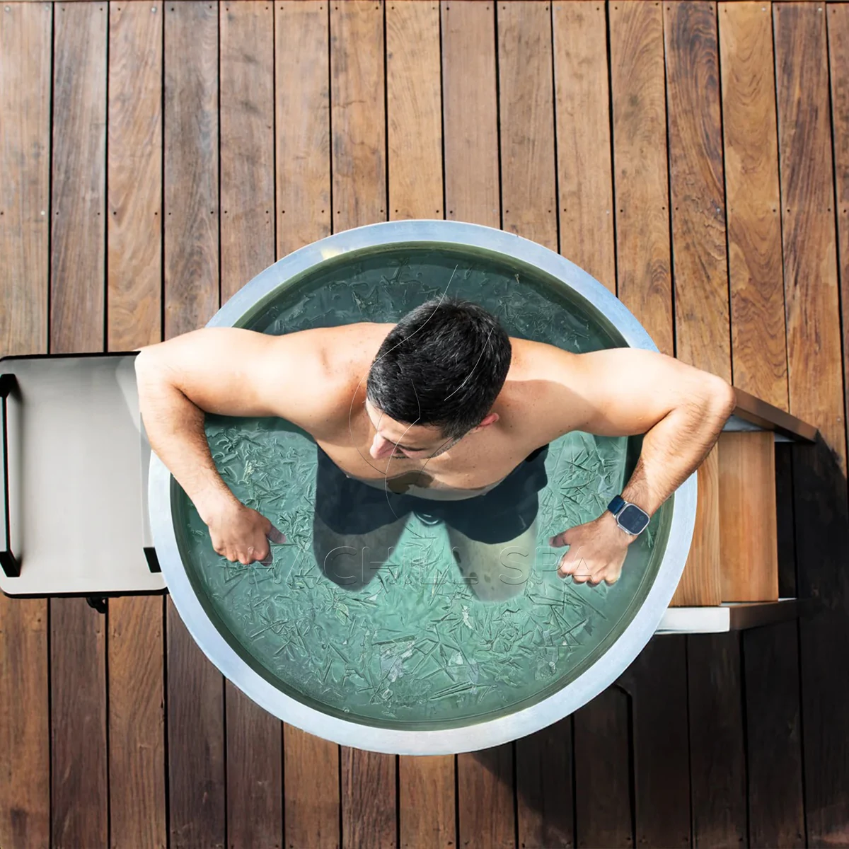
“Commercial” is not an operating specification.
A product may be offered for commercial projects, but the buyer still has to define the operating conditions that affect selection, supervision, cleaning, water management and closure responsibility.
Before releasing Upright for model-level comparison, establish enough of the operating case to answer:
Can this facility operate the station responsibly under its intended use pattern?
Separate Operating Assumptions From Product Claims
| Operating-duty input | Why it matters | Status |
|---|---|---|
| Intended use pattern | Defines the commercial case being screened | Defined / open |
| Supervision or access control | Defines part of the user-management boundary | Defined / open |
| Reset / cleaning responsibility | Shows who owns routine turnaround work | Defined / open |
| Water-management responsibility | Assigns testing, treatment and response | Defined / open |
| Closure authority | Identifies who can stop use | Defined / open |
| Reopening authority | Prevents unresolved problems from being ignored | Defined / open |
A venue label cannot fill these fields. Two facilities both called “gym,” “hotel” or “spa” can have very different staffing, operating hours, user patterns and reset responsibilities.
Venue-specific comparison therefore belongs in the Facility-Type Fit Guide. This guide only needs the operating case to be sufficiently defined for format qualification.
Treat Water and Reset Work as Qualification Gates
Commercial shared use also needs a credible owner for water management and reset work. That does not mean this page should prescribe one universal treatment programme, sanitation method or turnover requirement.
CDC currently lists Cold Plunge Resources within its Model Aquatic Health Code tools, including guidance for public cold-water venues such as cold plunges and ice baths. The MAHC remains guidance rather than federal law automatically governing every commercial cold-plunge project, so local adoption, facility classification and applicability still need project-specific review.
For the Upright buying decision, the useful question is:
Is the project’s water-management duty defined, assigned and routed to the correct technical or public-health owner?
A commercial operator should be able to identify who owns testing, treatment, routine cleaning, consumables and service, stop-use decisions and reopening decisions.
If those responsibilities are undefined, the commercial operating gate remains open.
Detailed filtration, sanitation and maintenance belong in the Cold Plunge Water Care Guide. Thermal and cooling-system performance belong in the chiller-matching review.
Here, both remain qualification gates, not substitute technical manuals.
Assign the Building, Plant and Delivery Interfaces Before Release
A commercial product decision is fragile when a critical project interface has no clear owner.
The Upright buying guide does not need to perform structural, electrical, drainage or refrigeration design. It should make sure the project knows:
- what interface needs to be addressed;
- who owns it;
- what evidence is still required;
- what its current status means.
Keep three statuses separate:
Assigned — the responsible party has been identified.
Verified — the required check or evidence has been completed.
Approved — the responsible project authority has accepted the result.
An assigned issue is not automatically verified, and a verified supplier input is not automatically project approval.
| Interface | Typical evidence | Responsible owner | Status |
|---|---|---|---|
| Structural / support | Site-specific support review | Qualified project professional | Assigned / verified / open |
| Wet area / drainage | Site layout and applicable requirements | Project / relevant trade | Assigned / verified / open |
| Electrical | Exact equipment plus applicable requirements | Qualified electrical professional | Assigned / verified / open |
| External cooling / plant | Selected equipment requirements and location | Supplier and project team within their respective scopes | Assigned / verified / open |
| Service access | Exact configuration and maintenance requirement | Product/project team | Assigned / verified / open |
| Delivery / removal | Product/packing information plus site route | Buyer/project/logistics owner | Assigned / verified / open |
For U.S. workplaces where OSHA requirements apply, walking-working-surface requirements can affect wet areas, and electrical working-space requirements can protect areas around electrical equipment. Those spaces should not be treated as generic unused floor simply because the product fits nearby.
That principle does not create one universal cold-plunge clearance. The exact project, equipment and applicable rules control the final requirement.
External Plant Is Still Part of the Project
HACHILL’s current CT12 and CT15 Upright product records both specify use with an external cooling system. The format decision therefore cannot stop at vessel dimensions.
Depending on the selected equipment and site, the project still has to coordinate the plant location, connections, service relationship and applicable electrical or environmental conditions.
The format-level question is:
Is the cooling/plant interface defined well enough for Upright to proceed?
Detailed thermal and hydraulic matching belongs in the Cold Plunge Tub and Chiller Guide.
Keep Delivery and Future Removal Visible
Delivery remains a legitimate commercial buying gate because a good installed location is not useful if the selected configuration cannot realistically reach it.
Record significant constraints such as narrow doorway conditions, tight turns, lifts or stairs, overhead restrictions, unusual orientation requirements, and future removal conditions that may change after fit-out.
This does not require a full logistics study inside the buying guide. It requires the buyer to avoid turning an unknown delivery path into an assumption.
If a delivery condition can change the format decision and is still unresolved, mark it HOLD.
Grade the Evidence and Make the Upright Go / Hold / Redesign Decision
A controlled buying decision depends not only on what evidence exists but on how closely that evidence matches the decision being made.
An exact, current configuration record is more useful for a model-specific decision than a category image. A controlled site measurement is more useful for that site than an assumed room dimension.
Use evidence specificity explicitly.
Clear Hard Disqualifiers Before Preference Scoring
Do not begin with an overall weighted score while a critical format gate is still failed or open.
| Qualification gate | Supported | Open | Incompatible |
|---|---|---|---|
| Upright format rationale | Continue | HOLD | Consider another format |
| User/access viability | Continue | HOLD | Redesign or another format |
| Complete-station fit | Continue | HOLD | Redesign or another format |
| Commercial operating duty | Continue | HOLD | Redesign operating case |
| Building / plant interfaces | Continue | HOLD | Resolve or redesign |
| Evidence specificity | Continue | HOLD | Obtain configuration-specific evidence |
This preserves one of the most useful rules in the original buying guide:
Clear hard failures before preference scoring begins.
A compact footprint, preferred material or attractive product design cannot compensate for a critical gate that the project has not resolved.
Use Exact Configuration Evidence Before Model Selection
Exact, current, configuration-specific evidence
Best suited to exact product and project decisions.
Category or related-model evidence
Useful for screening and discovering questions, but not automatically transferable.
Marketing or application imagery
Useful for orientation, not sufficient to establish configuration, compliance, clearance or performance.
Open assumption
Not evidence. Keep it visible until it is resolved.
This is an evidence-control method for the buying process, not an external industry grading standard or certification hierarchy.
PROCEED WITH UPRIGHT
Use this when the critical format gates are sufficiently closed for exact-model review. It does not mean final site approval. It means the Upright format has earned the next level of procurement evaluation.
HOLD — EVIDENCE MISSING
Use HOLD when a decision-changing field remains unresolved. A HOLD prevents an assumption from becoming an informal product promise.
REDESIGN — UPRIGHT MAY STILL WORK
Use REDESIGN when the issue may be solved by changing the project condition rather than abandoning Upright. Document the revised condition and reopen the affected gate.
EVALUATE ANOTHER FORMAT
Use this when a critical Upright-specific condition cannot reasonably be satisfied inside the defined project boundary. This is not a judgment that Upright is a poor product category. It means another body format may fit this project better.
If a decision-critical model, access arrangement, room condition, plant location or operating assumption changes, reopen the affected gates rather than automatically carrying the earlier PROCEED result forward.
Carry the Qualified Project Into Model-Level Review and RFQ
Passing format qualification does not finish the purchase decision.
It means the project is ready to compare exact Upright models without losing the assumptions that made the format viable.
Carry both confirmed inputs and unresolved conditions forward.
| Model-level / RFQ input | What to preserve |
|---|---|
| Application | Intended commercial use and operating boundary |
| Qualification result | PROCEED status plus conditional items |
| Installation area | Current site information and drawing/revision |
| User/access arrangement | Intended arrangement and open questions |
| Cooling-system status | Selected / planned / open |
| Water and drainage | Known interfaces and responsible owners |
| Delivery constraints | Relevant doorway, route or handling limitations |
| Site interfaces | Structural, electrical, service and other open responsibilities |
| Documentation | Evidence or project documents required by the buyer |
| Commercial scope | Quantity, destination and relevant customization/branding inputs |
| Change control | Conditions that require qualification to be reopened |
Once the format has qualified, the HACHILL Upright Cold Plunge range becomes the appropriate model-level owner. Exact CT12 and CT15 geometry, materials and listed configuration details should come from the current product records instead of being repeated from memory in the buying guide.
A project enquiry does not need every site field fully resolved before contact. Open items should remain visible.
For a HACHILL quotation, provide what is already known about intended application, model preference if any, quantity and destination, available installation area, access and delivery constraints, external cooling status, water and drainage context, and documentation or customization requirements.
For this defined commercial project, Upright has either passed the format-level gates and may proceed to exact-model review, or it remains on HOLD, requires redesign, or should be replaced by another format for clearly recorded reasons.
Request a HACHILL project quotation with the qualification record and any open conditions that could affect model selection.