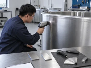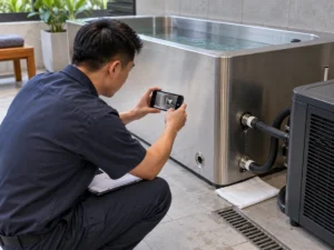
Direct answer: An upright cold plunge can reduce facility floor-space demand, but only when the complete installed station requires less plan area than a defined alternative. Compare like-for-like functions: vessel, entry and exit, accessories, cover movement, external plant, drainage, service and removal access, delivery, and any project-required keep-clear zones. Credit only validated overlaps, keep unresolved inputs open, and report the result for the exact product configuration and room revision being assessed.
A smaller tub diameter can reduce the vessel footprint. It is not, by itself, proof of a smaller completed installation.
For a commercial project, the useful question is therefore not simply “Is the Upright tub compact?” It is:
Does this exact Upright configuration require less installed room than the defined alternative after both options are compared on the same basis?
This page owns that verification task. Broad Upright-format qualification belongs in the Upright Cold Plunge Buying Guide; detailed entry ergonomics, facility-type fit, chiller matching, accessibility approval and exact product specifications remain with their dedicated owners.
Define What “Footprint” Means Before Comparing Space
“Footprint” can describe several different spatial quantities. Mixing them is one of the fastest ways to create a misleading space-saving claim.
For this article, use four working definitions:
| Spatial measure | What it describes | What it does not establish |
|---|---|---|
| Vessel footprint | The tub’s plan envelope | Complete installation size |
| Installed station footprint | The plan-area union of the spatial functions required by the selected station and configuration | Broader room or facility suitability |
| Usable room demand | The room area affected by operation plus relevant circulation or protected functions | That every part of the area is permanently exclusive |
| Verified space-saving delta | The like-for-like difference between two declared, configuration-specific installed-space comparisons | A universal saving for Upright tubs |
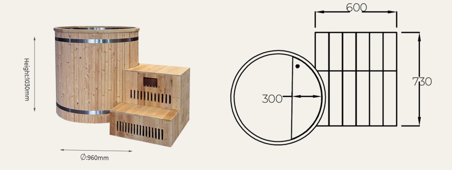
The distinction is practical. An Upright vessel may use less horizontal length while the completed station still needs room for entry, a step or support, cover movement, external cooling equipment, connections, service access or a protected route.
Current HACHILL Upright cold plunge model information makes the same boundary visible: product dimensions describe the tub envelope, while installation planning extends beyond the tub itself.
A compact vessel and a compact completed installation are separate claims.
Freeze the Comparison Baseline and Exact Configurations
A space-saving claim is incomplete until the project answers “compared with what?”
Define the Comparison Baseline
The baseline may be another shortlisted cold-plunge configuration or an existing installed layout. Either can work if both sides of the comparison use equivalent scope.
“Upright versus a normal cold plunge” is not precise enough. It does not establish the competing model or body format, included access components, external cooling arrangement, cover state, connection and service side, room revision, or delivery and removal assumptions.
| Comparison field | Upright option | Baseline option |
|---|---|---|
| Exact model/configuration | Confirmed / open | Confirmed / open |
| Product/drawing revision | ||
| Access components included | ||
| Cover state | ||
| External cooling/plant scope | ||
| Connection/service side | ||
| Room-layout revision | ||
| Delivery/removal state | ||
| Open assumptions |
The HACHILL Upright range illustrates why “Upright” alone is not a controlled configuration. CT12 and CT15 have different current external dimensions and different listed configuration details. Model-specific information belongs to the exact product record, not to a generic Upright assumption.
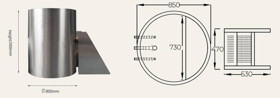
Photography is weaker evidence than an exact configuration record. A step or other component visible in an image should not automatically be treated as included in the quoted configuration.
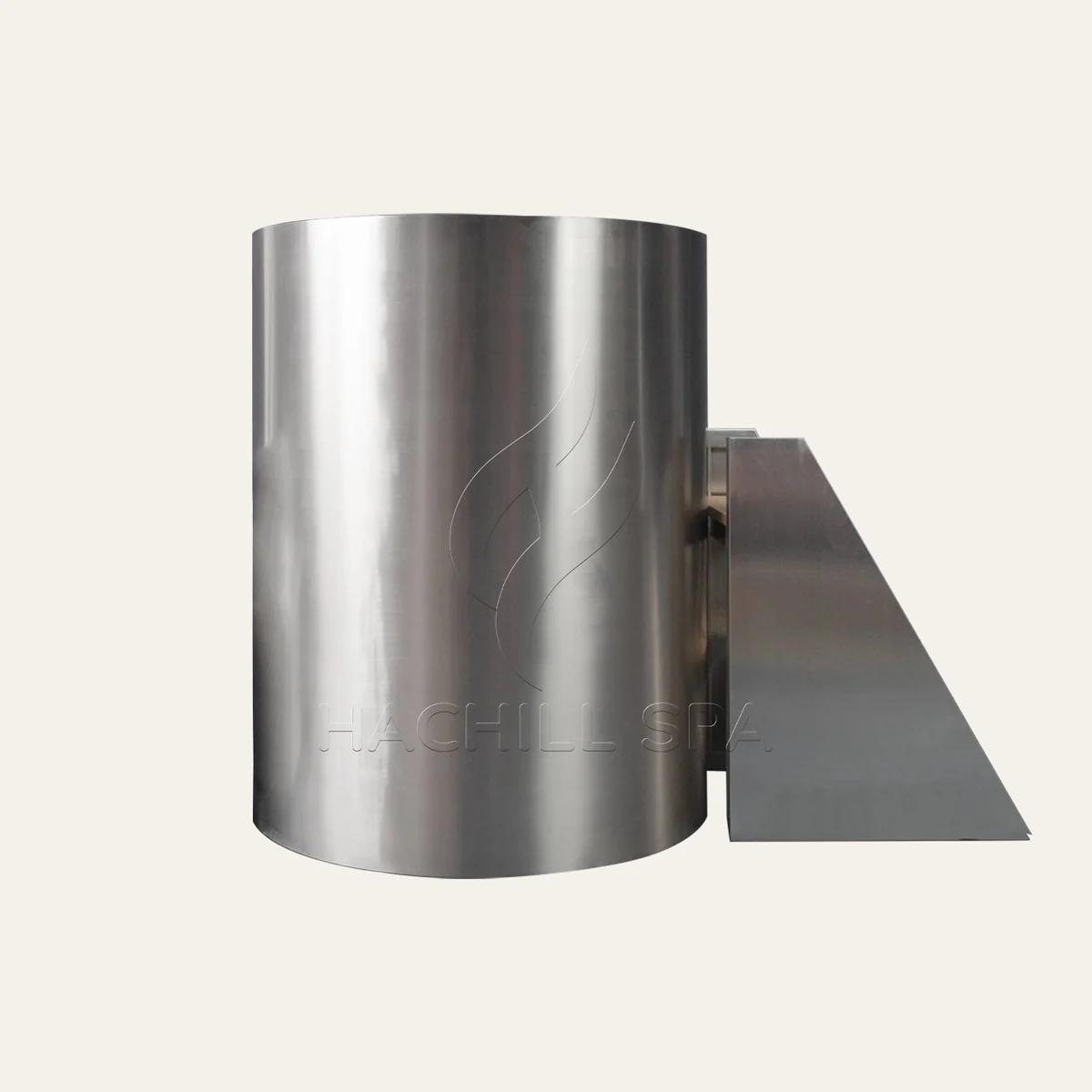
Keep Revision and Measurement Basis Visible
Use the same room coordinate system and comparison basis for both options. Record which datum each dimension comes from. Separate installed dimensions, packed dimensions, movable accessories, connection projections, service-side requirements and site measurements.
Do not replace a missing dimension with a value from another model simply because the products look similar.
The evidence itself should also be graded by specificity. An exact approved product record or controlled site measurement may support a geometry decision. A related-model photograph may only identify a question that still has to be closed.
If the model, accessory scope, plant arrangement or room layout changes, reopen the affected footprint conclusion. The space-saving result belongs to a configuration and revision, not permanently to the word “Upright.”
Build the Complete Installed-Space Ledger
After the comparison basis is frozen, identify every real function that consumes space around the selected station. Do not begin by drawing arbitrary clearance rectangles around the tub. Begin with the functions that actually have to occur.
| Zone | Evidence basis | Typical active state | Comparison treatment |
|---|---|---|---|
| Vessel/base | Exact product/configuration record | Always | Use exact envelope |
| Entry/landing | Project access arrangement | Each use | Count task space needed for the declared arrangement |
| Step/support/accessory | Quoted or approved scope | Use/reset | Confirm inclusion and stored position |
| Cover | Exact configuration/method | Open, closed or stored | Include the state that affects the room |
| External cooling/plant | Selected equipment documentation | Operation | Keep separate from the tub envelope |
| Connections/drainage | Coordinated project layout | Operation/service | Record route and interface |
| Service/removal | Exact service requirement | Planned closure/service | Preserve task and component-removal access |
| Wet/protected route | Applicable project requirement | Operation | Do not treat required route space as unused floor |
| Delivery/replacement | Packing/configuration evidence plus site route | Receiving/replacement | Treat as a temporary but real project state |
The ledger does not mean every installation uses every row. It means every counted area should have a function, evidence source and status.
Detailed user entry and exit analysis belongs to the Upright entry and ergonomics guide. This article only needs the resulting access zone as a spatial input.
In U.S. workplace settings where OSHA 1910.22 applies, walking-working surfaces must be managed for safe access and wet-process conditions, including drainage where wet processes are used. The rule does not create a universal cold-plunge landing dimension; it means project-required wet-route and walking-surface functions should not disappear from the plan simply because the tub fits.
Electrical working space follows the same logic. In U.S. workplaces where it applies, OSHA 1910.303 requires sufficient access and working space around electrical equipment and includes specific working-space rules for certain equipment. Applicability depends on the actual equipment and workplace, so any required electrical working zone should not be counted as spare floor area. Exact electrical design remains with the applicable rules and qualified project professionals.
Include Temporary Operating and Service States
A station does not exist in only one static state. The cover may move. A filter may have to be removed. A valve may need to rotate. A service panel may need to open. A failed component may eventually need a path out of the room.
Temporary states can therefore determine whether a compact concept plan remains workable after installation.
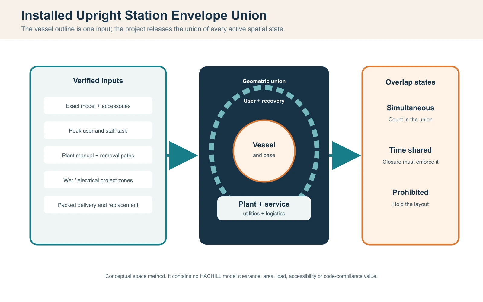
For each zone, record what function needs it, when the function is active, what evidence defines it, whether the geometry is confirmed or open, and whether another function is being proposed in the same area.
Decide Which Space Zones Can Actually Overlap
Two outlines occupying the same part of a drawing do not automatically create a space saving. The functions behind those outlines have to be compatible.
A user route cannot simply disappear because a service panel opens into it. A required equipment working space does not become permanent storage because maintenance is infrequent. An airflow path cannot be filled with furniture while the equipment depends on that path.
- Do the two functions occur at the same time? If yes, do not normally count them as shared space.
- Does an equipment manual, applicable requirement or project rule require one zone to remain available? If yes, preserve that space.
- If the functions occur at different times, is there a controlled operating state that prevents conflict? If no, keep the overlap unverified.
- Is the sharing assumption documented on the controlled layout? Only then should the overlap be credited within that defined condition.
This is a project decision method, not a statutory clearance formula.
For example, a service envelope may overlap part of a user area when service occurs only during a controlled closure and the equipment can still be accessed as required. “The technician is only there occasionally” is not enough.
Do not count one piece of floor twice unless the project can explain why both functions can genuinely share it.
This is where many apparently compact layouts fail. The vessel may be small; the drawing may also be double-counting the same surrounding space.
Calculate the Net Installed-Space Difference
Once the same scope has been applied to both options and the proposed overlaps have been validated, calculate the comparison from the complete installed geometry.
Installed plan-area demand = area of the geometric union of the required installed zones
Verified installed-space delta = baseline installed plan-area demand − Upright installed plan-area demand
These expressions describe the project comparison method. They are not an industry-standard product-sizing formula.
Compare Like-for-Like States
If the baseline includes the vessel, entry/access space, external plant, service access and cover movement, the Upright option must include the equivalent required functions.
Do not compare a fully installed baseline station with only the Upright tub diameter.
Do not simply add the area of every rectangular zone either. Geometrically overlapping zones should be counted once in the physical union.
But there is an equally important second rule: do not subtract an overlap until the functional-overlap test has passed.
| Comparison item | Baseline | Upright | Evidence state |
|---|---|---|---|
| Vessel plan envelope | Confirmed / open | ||
| Required installed zones | Confirmed / open | ||
| Validated overlaps | Confirmed / open | ||
| Installed geometric union | Confirmed / open | ||
| Open spatial interfaces | Listed separately | ||
| Verified delta | Report after material inputs close |
Keep Open Inputs Out of the Verified Saving
An unresolved chiller location is not zero area. A service path that has not been verified is not free space. An unknown access arrangement cannot be converted into a precise percentage.
Keep material unknowns visible until they are closed. If a conditional range is used, its bounds also need evidence.
This is why a statement such as “Upright cold plunges save X% of facility space” is not defensible as a universal claim. The result changes with exact models, access arrangement, external plant location, room geometry, service state, cover arrangement and validated overlaps.
Check Whether the Space Saving Creates a New Constraint Elsewhere
A smaller vessel can shift a constraint instead of eliminating it.
A Smaller Footprint Does Not Prove Structural Suitability
Floor-area reduction and structural suitability are separate checks. The filled vessel, user, accessories and supporting base still impose loads on the actual structure, and a more compact support area can change how those loads are introduced into it. Keep structural verification outside the footprint delta and use the project’s site-specific structural criteria rather than inferring floor capacity from tub diameter or room fit.
External Plant Can Move the Space Requirement
Current HACHILL Upright models are planned with an external cooling-system interface. The tub and cooling equipment therefore cannot be treated as one compact vessel envelope.
A chiller placed outside the wellness area may reduce visible equipment in that room, but the equipment still needs an acceptable location, connections and service state elsewhere.
The right question is not “Can we move the chiller out of this room?” It is: “Does the complete project still work after the plant envelope and its interfaces move?”
Detailed cooling-system matching belongs in the cold plunge tub and chiller matching guide.
Service Space Can Appear Only After Fit-Out
A cabinet or screen can make a concept drawing look clean while preventing filter removal, valve operation, panel opening or normal component replacement. That hidden service requirement should remain part of the footprint decision even if it is needed only during planned closure.
Delivery Is Three-Dimensional
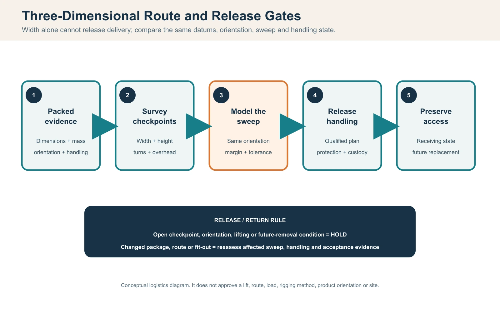
Installed diameter does not verify delivery. A packed unit can pass the narrowest doorway and still fail at the next corner, a stair or lift, a low overhead service, an orientation change or the final assembly position.
Future component or product removal can create the same problem after furniture and finishes are installed.
Vertical Space and Access Still Need Review
Reducing horizontal vessel length does not automatically solve cover movement, overhead conflicts, vertical access conditions or surrounding user movement. Those conditions remain configuration- and site-specific.
Accessibility is also a separate conclusion. A smaller footprint does not establish accessibility compliance. In U.S. projects subject to the ADA Standards, the responsible design team should determine which provisions apply to the specific facility and how the cold-plunge feature is classified before setting route or entry requirements; the U.S. Access Board ADA Standards are an authoritative starting point. Other jurisdictions use their own rules.
Where did the supposedly saved space go?
If it moved into an external plant room, an invalid shared route, omitted maintenance access or an unchecked delivery path, the project has not yet demonstrated a net space saving.
Later fit-out changes matter too. Furniture, screens or storage can consume areas that were originally relied on for service or user movement. When a controlled zone or overlap assumption changes, reopen the affected comparison.
Turn the Verified Layout Difference Into an RFQ and Acceptance Record
The final result should survive procurement. Do not send a supplier only the statement, “We need a compact Upright cold plunge.” Send the basis of the footprint decision.
| RFQ / record field | Buyer/project input | Supplier/project response | Reopen trigger |
|---|---|---|---|
| Exact configuration | Target model and options | Exact quoted scope, revisions and exclusions | Model/option change |
| Comparison baseline | Defined alternative or existing layout | Deviations affecting comparison | Baseline change |
| Room/layout | Controlled plan, datums and revision | Product-side interface information | Site/furniture change |
| Entry/access scope | Required arrangement | Included/excluded components | Access arrangement change |
| External plant | Location and current system status | Exact product/interface scope where applicable | Equipment/location change |
| Service/removal | Required service state | Exact product-side service information | Service-side change |
| Overlap assumptions | Which zones are shared and why | Conflicts or deviations | Operating-method change |
| Open items | Owner and status | Evidence/deviation response | New unresolved interface |
| Evidence control | Revision controlling comparison | Updated controlled documents | Configuration revision |
Keep responsibility boundaries explicit. The supplier can provide exact quoted product/configuration data and included scope. The project team remains responsible for site-specific building, room and regulated interfaces. The buyer or operator owns the operating assumptions used in the comparison. A supplier product statement should not silently become project approval.
The same comparison basis should survive into the final installed review. If the model, access arrangement, cooling equipment, cover, service route or room configuration changes, identify the affected zones and repeat the relevant verification instead of keeping an obsolete “space-saving” conclusion.
Preserve superseded or failed records beside the corrected revision rather than overwriting them; the earlier record shows which evidence controlled the original decision.
For a HACHILL quotation, provide the preferred model/configuration, quantity and destination, available installation area, relevant delivery constraints, intended entry arrangement, cooling-system status, water/drainage interfaces, any known site structural constraints, and any documentation or branding requirements that affect the order.
The useful final statement is specific rather than promotional:
For this declared configuration, baseline, room revision and set of validated overlap assumptions, the Upright option has—or has not—produced a verified installed-space advantage.
Request a HACHILL quotation with the controlled layout and configuration inputs that affect the comparison.