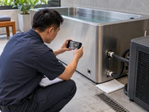
Yes, a cold plunge system may be left powered 24/7 if the exact equipment is designed and approved for that operating schedule—but “powered on” does not mean the refrigeration compressor is running at full cooling output 24/7. Controls, circulation and treatment may continue while a fixed-speed compressor cycles with demand. A variable-speed or other capacity-modulating compressor may instead run for long periods at reduced output.
Continuous compressor operation is therefore not a diagnosis by itself. During initial pull-down or recovery, a long run can reflect a real cooling load. During a comparable holding period, a new long-run pattern can justify investigation if the required water condition is not being maintained or the operating behavior has changed.
For diagnosis, separate three questions:
- Which component is actually running—and, if the compressor modulates, at what operating state or load?
- Is the system in pull-down, holding or recovery?
- How much compressor runtime and whole-system electrical energy are being recorded under that declared condition?
That distinction is more useful than simply saying, “The chiller runs all the time.”
Should a Cold Plunge Chiller Run 24/7?
There is no universal 24/7 rule for every cold plunge chiller.
Some systems are intended to remain energized so controls, circulation or other functions can operate as designed while refrigeration responds to cooling demand. In a fixed-speed design that response may be on/off cycling; in a variable-capacity design it may include longer operation at reduced output. Other systems may have different operating schedules, environmental limits or shutdown requirements.
This distinction prevents an apparent 24/7 run condition from being diagnosed too quickly. Before deciding whether operation is normal, identify which component is active, whether compressor capacity is fixed or modulating, what duty case is occurring and whether the required operating condition is actually being met.
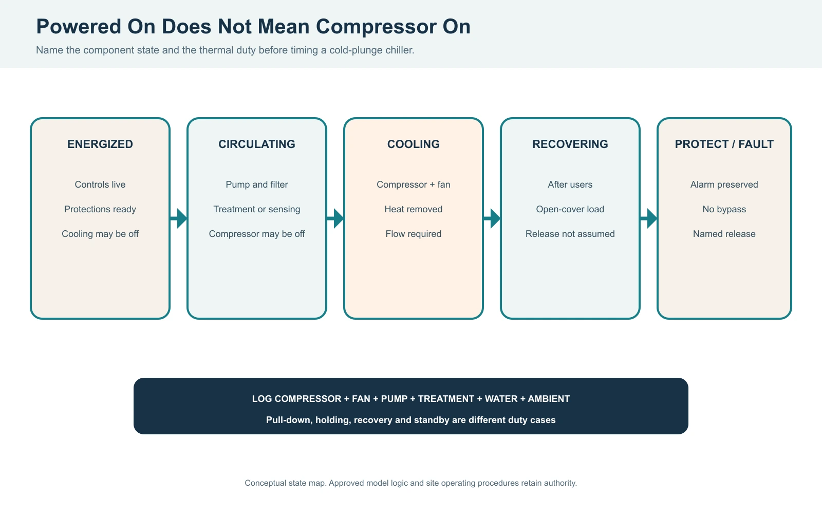
What Actually Runs When a Cold Plunge System Stays On?
“The chiller is running” is too vague for useful diagnosis.
A cold plunge system can contain components with different operating schedules.
| Observed state | What it can tell you | What it does not prove |
|---|---|---|
| System energized | Controls or other electrical functions are available | The compressor is running |
| Water circulating | The pump or water loop is active | Refrigeration is active |
| Active refrigeration | Cooling is being called for or provided | The chiller is correctly sized |
| Protection or fault state | The equipment has responded to a condition or limit | The root cause is known |
The exact component sequence is model-specific. A circulation pump, fan, treatment device or other component may operate independently of compressor runtime depending on the system design.
Sound is therefore weak evidence by itself. Hearing equipment operate does not identify which component is running.
For the rest of this guide, compressor duty cycle refers to compressor runtime, not total system power-on time and not pump runtime.
Fixed-speed and variable-capacity compressors need different interpretation
For a conventional on/off compressor, runtime percentage can be a useful first description of how often refrigeration is active. It still needs the duty case and operating conditions before it can be judged.
For a variable-speed or otherwise capacity-modulating system, runtime percentage alone is weaker evidence. The compressor can remain on while its speed, refrigerant flow and cooling capacity change with load. Danfoss, for example, describes variable-speed compressor control as a way to match capacity to actual demand during part-load operation.
When modulation is available, record the approved load/speed signal or measured electrical trend if the equipment exposes it. Do not treat 100% runtime at reduced output as equivalent to 100% runtime at full output.
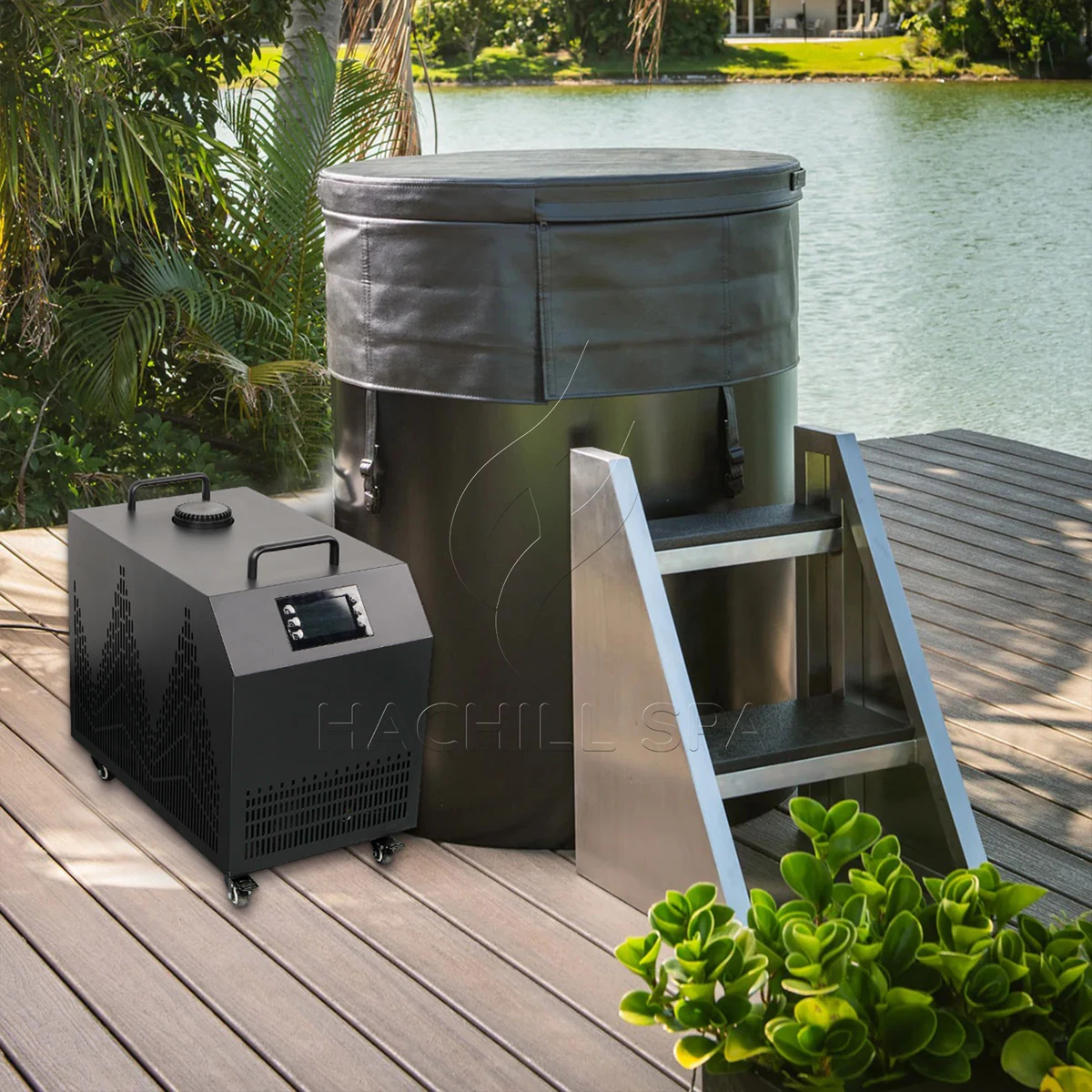
How to Measure Cold Plunge Chiller Duty Cycle Correctly
For an on/off compressor, compressor duty cycle is the percentage of a defined observation period during which the compressor is actually running. For a modulating compressor, the same percentage does not describe how much cooling capacity was delivered during that runtime.
The calculation is easy. Getting meaningful input data is more important.
Measure the correct state
Record active compressor or cooling-call time rather than the number of hours the entire cold plunge remains switched on.
Where the equipment provides an approved status signal or control record, that is more useful than inferring compressor state from sound or a general display icon. If the compressor modulates, retain the available speed, load or power information rather than reducing the whole record to on/off time.
Declare the observation period
A duty-cycle percentage without its observation period is incomplete.
There is also no universal observation length that makes a cold-plunge duty-cycle measurement automatically representative. The period should match the operating condition being evaluated.
A reading collected only during initial cooldown should not be presented as though it represents stabilized daily operation.
Record the duty case
Label the period being measured as:
- pull-down;
- holding; or
- recovery after additional load or use.
These conditions can produce very different refrigeration demand.
Keep the context with the number
Record relevant conditions alongside compressor runtime, especially changes in ambient conditions, cover use, flow/filter condition, condenser airflow or operating schedule.
A useful record therefore looks like:
Keep a synchronized operating log
The minimum useful log keeps the runtime observation and its context on the same time base.
| Log field | What to record |
|---|---|
| Time | A timestamp or elapsed-time point for the observation |
| Compressor state | Whether active compressor or approved cooling operation is present |
| Duty case | Pull-down, holding or recovery |
| Operating condition | The relevant water or site condition being compared |
| Event or change | A relevant change such as cover use, flow/filter condition, ambient condition, user event or alarm |
This keeps a later comparison tied to the condition that produced it instead of leaving a percentage without context.
“The duty cycle was 70%” is not enough by itself. Seventy percent is not automatically good, bad, oversized or undersized; it is an observation that still needs context.
What Does Long Compressor Runtime Mean During Pull-Down, Holding and Recovery?
The same compressor runtime can mean different things under different thermal conditions.
| Duty case | What the system is doing | How to interpret long runtime |
|---|---|---|
| Pull-down | Moving warmer water toward the operating condition | Longer operation may reflect the larger initial cooling load |
| Holding | Maintaining an established operating condition | A change from a comparable baseline can be diagnostically useful |
| Recovery | Returning toward the operating condition after additional load | Longer operation may reflect the added recovery load |
Micro decision case: A long compressor run during a declared pull-down should first be judged against that pull-down duty. If a similarly long pattern later appears during a comparable holding period and the required operating condition is no longer being met, investigate the changed load or system condition before treating capacity as the answer.
Pull-down
During pull-down, the system is removing stored heat while moving the water from a warmer starting condition toward its operating target.
Long uninterrupted refrigeration during this period does not, by itself, show that the chiller is undersized.
Instead, judge whether the system is making appropriate progress under the declared load and site conditions.
Holding
Once the system is operating in a stable range, compressor behavior becomes easier to compare over time.
If a fixed-speed system previously cycled under one set of conditions but later runs much longer, investigate what else changed before blaming capacity. For a variable-capacity system, compare the operating signal or electrical trend as well as elapsed runtime.
Ambient conditions, cover use, water-side flow and condenser-air conditions can all change the operating load. For a deeper look at this variable, see HACHILL’s guide to ambient temperature and cold plunge pull-down time.
Recovery
Recovery begins after the established system receives additional load and needs to return toward its operating condition.
For a commercial facility, this distinction is especially important. An overnight pull-down record does not prove that the system can recover between repeated operating events.
Do not combine pull-down, holding and recovery into one daily percentage and call that a universal “normal duty cycle.” Separate the cases first.

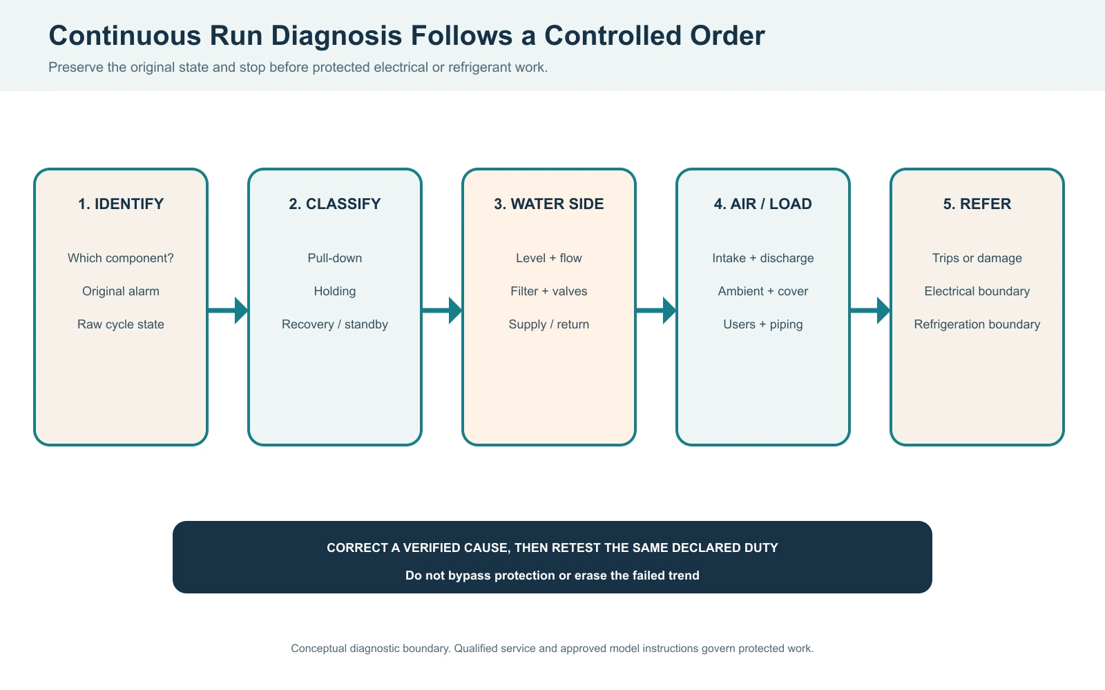
When Should Continuous Compressor Running Trigger Investigation?
Continuous compressor operation deserves closer investigation when it is not explained by the approved control strategy or duty case, when operating behavior has materially changed, or when the system cannot meet the required operating condition. A variable-speed compressor may legitimately remain on at part load, so runtime alone is not enough.
Start with observable conditions and the exact control logic before assuming a refrigeration failure or sizing problem.
1. Confirm the duty case
Determine whether the system is still pulling down, holding a stable condition or recovering from additional load.
A long run during a high-load period and a long run during an otherwise stable holding period are not the same diagnostic event.
2. Check observable water-side conditions
For applicable systems, reduced or restricted flow can interfere with normal operation.
Check external conditions such as the filter state, visible circulation and the approved valve configuration before moving into deeper diagnosis.
Do not invent a universal flow threshold. Exact flow limits belong to the specific equipment documentation.
3. Check condenser airflow and site conditions
Air-cooled refrigeration depends on being able to reject heat.
Blocked airflow, poor ventilation or warm discharge air recirculating toward the condenser intake can change operating performance. Exact clearances and ambient limits remain equipment-specific rather than universal cold-plunge numbers.
4. Compare against a relevant baseline
A changed runtime pattern is more useful than an isolated observation.
Compare the current run with earlier operation under reasonably comparable duty, ambient, flow and cover conditions.
If a correction is made, change one verified variable at a time and repeat the relevant duty case. A corrected test under different conditions should not be presented as though it reproduced the original failure.
5. Treat frequent starts and stops separately
Repeated short cycling can matter, but there is no universal “X minutes” rule for every compressor.
The 2026 ASHRAE Refrigeration Handbook cautions against compressor short cycling and directs users to compressor-manufacturer literature for applicable cycle limits rather than providing one universal starts-per-hour rule.
Identify abnormal cycling as something to investigate, but do not invent one generic minimum runtime or starts-per-hour limit.
6. Stop when troubleshooting becomes electrical or refrigerant service
User-level observation should end before internal electrical or refrigerant work begins.
In U.S. workplace settings, OSHA 1910.333 generally requires exposed live parts to be deenergized before work unless defined exceptions apply, and work on energized equipment is limited to qualified persons.
For U.S. stationary refrigeration equipment, EPA Section 608 technician-certification requirements apply to specified service activities that could release refrigerant.
Other countries and installations have their own requirements, so the exact equipment instructions and applicable local rules still govern.
If it remains unexplained, move to qualified technical diagnosis rather than guessing from runtime alone.
How to Calculate Whole-System Cold Plunge Energy Use
Electrical power and electrical energy are different quantities.
The U.S. Energy Information Administration describes watts and kilowatts as units of power, while watt-hours and kilowatt-hours measure electrical energy used over time.
That distinction matters because a cold plunge can contain several electrical loads operating on different schedules.
This multiplication is appropriate when the power value represents the component over the period being calculated. If a compressor, pump or fan modulates materially, use interval power data or a suitable energy meter rather than assuming one constant input value.
For example:
Refrigeration energy = refrigeration input power × refrigeration runtime
Circulation energy = pump input power × pump runtime
Auxiliary energy = auxiliary input power × auxiliary runtime
Then add the applicable energy values.
The inputs should come from the exact equipment documentation or suitable measurements—not from a generic “typical chiller” wattage. Do not substitute rated cooling capacity for electrical input power; they are different quantities.
Why nameplate power × 24 hours can be misleading
If refrigeration cycles rather than running continuously, multiplying refrigeration input by 24 hours can overstate compressor energy use.
The opposite error is also possible. Calculating compressor consumption alone may understate whole-system energy if circulation or other loads continue when refrigeration is off.
Component runtime therefore belongs in the energy calculation.
A variable-based energy example
If:
- representative refrigeration electrical input = Pr
- refrigeration runtime = tr
- representative circulation electrical input = Pp
- circulation runtime = tp
then:
This preserves the calculation method without pretending that one pump wattage, compressor wattage or duty-cycle percentage represents every system. Where power changes continuously, metered kWh over the declared period is usually stronger evidence than a single assumed wattage.
Why there is no universal daily kWh or electricity-cost figure
Actual energy use varies with equipment, operating schedule, compressor runtime, circulation schedule and operating conditions.
Electricity cost introduces another variable: the applicable tariff.
For broader budgeting, the HACHILL cold plunge cost guide owns the complete operating-cost boundary rather than this runtime article.
Also keep three quantities separate:
Confusing them can produce incorrect operating-cost and equipment-sizing conclusions.
When Should Runtime Data Lead to a Capacity Review?
Runtime becomes a capacity-review input only after the operating condition has been defined and obvious system or site causes have been bounded.
Do not use:
long runtime → undersized chiller
or:
short cycling → oversized chiller
as automatic decision rules. Control strategy, modulation capability, sensor behavior, flow, site load and equipment protections can all change the observed run pattern.
A more defensible sequence is:
If the question becomes whether chiller capacity should change, continue to the dedicated HACHILL chiller capacity-change guide. That sibling owns the decision to keep, correct and retest, review capacity or hold for more evidence.
If the task is instead to calculate or select cooling capacity from the beginning, use the cold plunge thermal engineering and chiller-sizing guide.
Those are different decisions from measuring runtime.
Frequently Asked Questions
Should I leave my cold plunge chiller on all the time?
There is no universal rule for every system. Follow the exact equipment instructions. A cold plunge may remain energized or circulating while its refrigeration compressor cycles only when cooling is required, so continuous system power does not automatically mean continuous compressor operation.
Is it normal for a cold plunge chiller compressor to run continuously?
It can occur during a high cooling load such as pull-down or recovery, and some variable-speed systems may also run continuously at part load. Investigate when the approved control strategy and duty case do not explain the pattern, the system is no longer meeting its operating objective, or behavior has changed from a comparable baseline.
What is a normal cold plunge chiller duty cycle?
There is no universal ideal percentage. For an on/off compressor, measure compressor-on time over a declared observation period and interpret it with the duty case and operating conditions. For a modulating compressor, runtime percentage alone is incomplete; retain available speed, load or power information.
Why does the pump keep running when the water is already cold?
Some systems use circulation independently of active refrigeration, but the operating sequence is model-specific. Pump operation alone does not prove that the compressor is running. Check the approved control sequence for the exact system.
How do I estimate daily cold plunge electricity use?
Calculate each significant electrical load from representative input power and actual runtime, then add the results. If power varies materially, use interval or metered energy data. Use model-specific or measured values and the applicable electricity tariff if you also want an operating-cost estimate.
Use Runtime as Evidence, Not as a Shortcut
Cold-plunge runtime becomes useful only after the operating state is defined.
Separate system power, circulation and active refrigeration. For on/off compressors, measure duty cycle within a declared operating case; for modulating compressors, preserve available load, speed or power information as well. Compare changed behavior against relevant conditions, and calculate electrical energy from the separate loads that actually operate.
That produces evidence that can support a troubleshooting decision.
It does not turn one percentage, one noisy pump or one long compressor run into an automatic capacity verdict.