HACHILL COLD PLUNGE GUIDE · TEMPERATURE & OPERATING CONTEXT
Direct answer: There is no single universally optimal cold-plunge temperature. A useful research reference band is around 10–15°C (50–59°F), while published cold-water-immersion studies also include colder conditions. Treat 10–15°C as evidence context—not a universal “best” temperature, a personal prescription, or proof that colder water is better.
The more useful way to think about cold-plunge temperature is to separate three questions: what research protocols commonly use, what temperature is actually being measured in the water, and what is appropriate for a particular exposure context. Those questions are related, but they are not interchangeable.
This guide explains what the commonly cited temperature range really means, why colder is not automatically better, how exposure time changes the context, and why a chiller setpoint is not necessarily the temperature a user experiences.
What Temperature Should a Cold Plunge Be?
A useful research reference band is around 10–15°C (50–59°F). Cold-water-immersion research also includes temperatures below this band, so 10–15°C should be understood as evidence context rather than a universal threshold, personal prescription or equipment requirement.
Current evidence has not established one temperature that is best for every user, purpose or outcome. Studies differ in participant population, immersion duration, immersion depth, exercise context and the result being measured.
A research protocol answers a research question under defined conditions; it does not automatically become an individual exposure recommendation.
The practical takeaway is therefore not to chase the lowest possible temperature. First understand what the temperature number represents, then consider exposure time, user context and the actual measured water condition.
What Does the Commonly Studied Cold-Plunge Temperature Range Actually Mean?
The 10–15°C (50–59°F) band appears frequently in cold-water-immersion research, particularly in sports-recovery protocols. Published studies also use colder conditions, so the research literature should not be reduced to one fixed temperature range.
Repeated use of similar protocols makes study comparisons easier, but it can create a misleading shortcut: frequently studied does not mean scientifically established as optimal.
A 2025 systematic review of cold-water immersion in healthy adults included studies using temperatures from roughly 7°C to 15°C and noted that the evidence base remains insufficient to define an optimal CWI protocol.
A newer 2026 temperature-dependent recovery systematic review and meta-analysis compared studies using approximately 5°C, 10°C and 15°C. Differences between temperature subgroups were not statistically significant, so the study did not establish one of those temperature bands as superior. The authors also describe the temperature subgroup analyses as exploratory, which is another reason not to turn a subgroup result into a universal prescription.
Much of the temperature-specific evidence also comes from post-exercise recovery, including soreness, performance and muscle-damage outcomes. Results from those settings should not be silently expanded into claims about every wellness goal or every user population.
| What the range can mean | What it does not mean |
|---|---|
| A common reference band in CWI research | A universal best temperature |
| A useful basis for comparing research protocols | A personal medical prescription |
| A temperature context used in recovery research | Proof that every benefit peaks in this range |
| A practical reference for discussing equipment requirements | Proof that colder or warmer settings are unsuitable |
The number is therefore most useful as evidence context: it helps readers interpret research and helps project teams describe an operating requirement, but it does not settle every exposure decision.
Is a Colder Cold Plunge Always Better?
No. Current evidence does not show that making a cold plunge progressively colder automatically improves the outcome.
Recent temperature-specific post-exercise research comparing very cold and more moderate immersion conditions has not established that the coldest condition performs best.
That does not prove that warmer cold water is universally better either. It means the evidence does not support a simple rule in which lower temperature automatically produces a greater desired benefit.
The distinction between intensity and efficacy matters. Colder water may feel dramatically more severe, but stronger sensation is not evidence of a better recovery result.
A 2025 peer-reviewed review of human cold adaptation and cold-shock responses describes substantial respiratory and cardiovascular responses at the onset of cold-water immersion. That evidence supports treating cold intensity as a safety consideration rather than as proof of greater benefit.
So the useful question is not, “How low can the chiller go?” It is, “What water condition fits the intended use without assuming that greater cold intensity produces a better result?”
Why Temperature and Exposure Time Need to Be Considered Together
Temperature is only one part of a cold-water-immersion protocol. Exposure time matters too.
Research protocols normally specify several variables together: water temperature, immersion duration, immersion depth, participant population and the outcome being studied.
A 2022 systematic review, meta-analysis and meta-regression of post-exercise cold-water immersion examined temperature and duration within recovery protocols and did not establish a simple universal formula that converts one water temperature into one correct exposure time for every person.
Longer exposure is not automatically better either. A temperature such as 10°C or 15°C describes part of the water condition; it does not define the complete exposure.
Readers deciding how long to cold plunge should therefore treat duration as a separate decision that must be interpreted alongside measured water conditions and the other relevant safety factors. For detailed session-duration guidance, use the dedicated duration guide.
Cold Plunge Setpoint vs. Actual Water Temperature
A chiller setpoint is the desired control target. It does not, by itself, prove the temperature of every part of the water in the tub or the condition a user experiences at a particular moment.
Controller documentation can distinguish the selected setpoint from the temperature measured by the controller sensor. For example, Aqua Logic DC-series controller instructions separately describe the selected setpoint and the displayed current water temperature, and show an on/off differential around the control target for that specific controller.
That example demonstrates a control principle; it is not a claim that HACHILL uses the same controller.
Sensor location also matters. ASHRAE Fundamentals of Control defines the set point as the desired value of the controlled variable and explains that a sensor measures that controlled variable for feedback. Applied to a cold-water system, a displayed sensor value should therefore be interpreted according to where and how that sensor measures the water.
This is a general measurement and controls principle, not a claim that every cold plunge develops a meaningful temperature gradient or that one sensor arrangement applies to every HACHILL system.
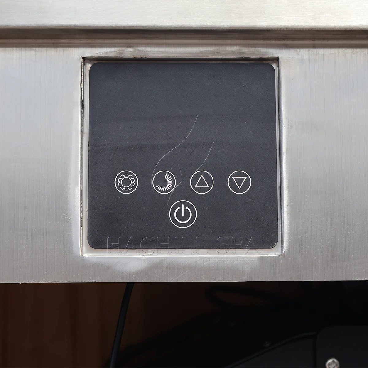
- Distinguish the selected setpoint from the displayed measured temperature.
- Identify where the controller sensor measures the water.
- Where user-zone temperature matters, verify the water condition at a representative measurement location under a defined operating state.
- Record the measurement location and system state when comparing readings.
- If a project requires independent verification, define the instrument, measurement location, timing and acceptance tolerance before comparing readings.
- Do not assume that a controller’s lowest selectable setpoint proves the complete system can reach and hold that water condition at every site.
Key equipment distinction: controller capability ≠ representative water temperature ≠ personal exposure guidance.
For cooling-capacity, pull-down, holding and recovery questions, continue to the cold-plunge chiller-sizing guide .
What Temperature Information Should Buyers and Facilities Specify?
A useful equipment brief needs more than: “The chiller must go down to 5°C.”
The buyer first needs to define what water condition the project requires, where that temperature is measured and under what operating conditions it must be maintained.
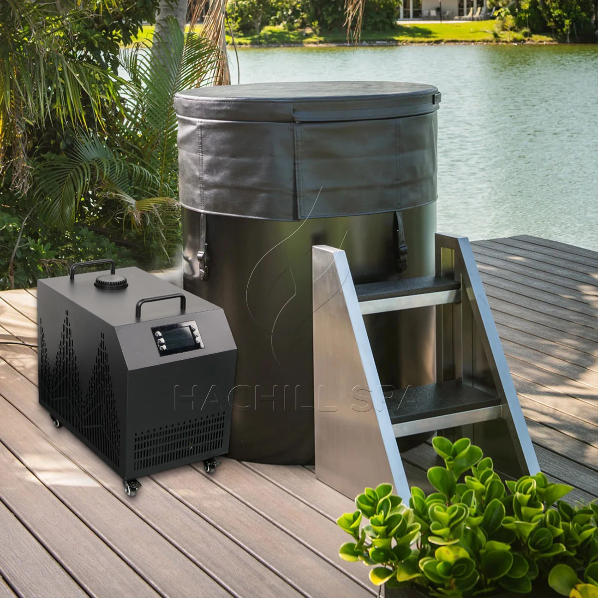
- Target operating temperature or operating band: the intended water condition, not simply the lowest number shown on a controller.
- Measurement basis: where the governing temperature will be measured and which reading will be used for routine operation or project verification.
- Water volume and starting condition: inputs that affect the cooling duty required to reach the target.
- Use schedule: occasional use, repeated sessions and commercial turnover create different operating demands.
- Operating-state definition: state whether the temperature requirement applies after stabilization, during normal use, after expected turnover or at another defined system state.
- Verification method: define the instrument, measurement location, timing and project-specific acceptance tolerance used for commissioning or routine checks.
- Site environment: ambient and installation conditions affect the thermal load the cooling system has to manage.
- Selected tub and cooling configuration: suitability must be verified for the exact equipment and stated project conditions.
These inputs also separate responsibilities. The buyer or facility defines the intended water condition and operating use case. The equipment supplier verifies what the exact offered configuration can support under those project conditions. The operator owns the site’s routine operating and measurement policy. Individual health or exposure guidance remains separate from the equipment specification.
If the tub or model is still open, continue to the HACHILL Cold Plunge category to narrow the product route.
If the target operating condition is already defined and the question is whether the cooling system can meet the required pull-down, holding and recovery duty, continue to the cold-plunge chiller-sizing guide .
Frequently Asked Questions
What temperature should a cold plunge be?
Around 10–15°C (50–59°F) is a commonly studied reference band, but it should not be treated as a universal personal target. Research also uses colder conditions, and no single temperature has been established as optimal for every user or outcome.
Is 10°C too cold for a cold plunge?
A temperature number alone cannot determine whether an exposure is appropriate for a particular person. Ten degrees Celsius appears in cold-water-immersion research, but research protocols are not universal personal safety prescriptions.
Is a colder cold plunge better?
Not automatically. Current temperature-specific recovery research has not established that the coldest water condition consistently produces the best outcome. Greater cold intensity should not be treated as proof of greater efficacy.
Is the chiller setpoint the same as the actual water temperature?
Not necessarily. A setpoint is a control target, while a displayed temperature comes from a particular sensor and measurement location. Interpret the reading according to the actual controller, sensor position and operating condition.
Does cold-plunge duration change how temperature should be interpreted?
Yes. Temperature and exposure time are separate protocol variables and should be considered together. A water temperature does not define the complete exposure or create one universal session duration.
Reference Basis
- 2025 systematic review and meta-analysis of cold-water immersion in healthy adults — temperature context, protocol variability and evidence limits around defining an optimal CWI protocol.
- 2026 temperature-dependent CWI systematic review and meta-analysis — temperature-specific post-exercise recovery evidence and the absence of a confirmed superior temperature subgroup.
- 2022 CWI systematic review, meta-analysis and meta-regression — temperature, duration and post-exercise recovery evidence boundaries.
- 2025 review of human cold adaptation and cold-shock responses — respiratory and cardiovascular cold-shock-response context.
- Aqua Logic DC-series controller instructions — example of the distinction between a selected controller setpoint and the water temperature measured by its sensor; not a HACHILL component claim.
- ASHRAE Handbook — Fundamentals of Control — general measurement context for locating sensing elements where the measured condition is representative of the controlled variable.
Scope: This article explains cold-plunge temperature evidence, measurement and equipment-specification boundaries. It does not provide individualized medical advice or claim that one temperature is universally optimal or safe.
Define the Water Condition Before You Size the System
For a commercial or project enquiry, provide the target operating temperature or band, measurement basis, selected tub or water volume, site conditions, use schedule and cooling-system status. Define the operating state and verification method when temperature acceptance matters. That keeps product selection and thermal-duty review separate from individual exposure guidance.
Request a Project Review