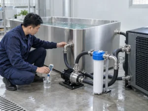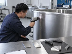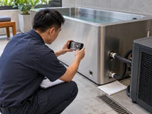
A practical engineering guide to tub drain-down, floor drainage, waterproofing, condensation, discharge routes, freeze protection and commissioning.
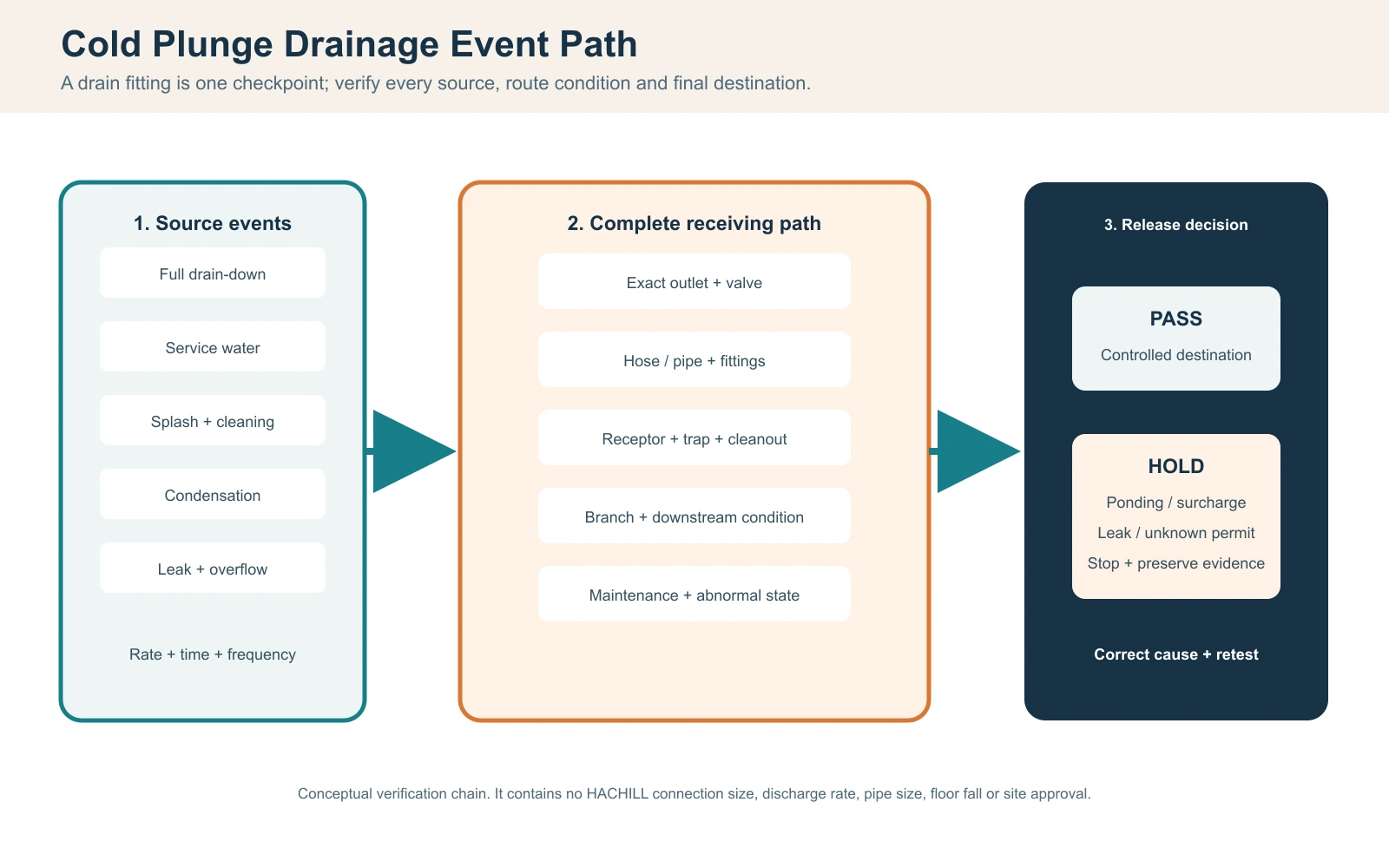
Direct answer: Plan a laydown cold plunge around six water paths: full tub drain-down, equipment-service water, splash and cleaning, condensation, abnormal leakage or overflow, and freeze drain-down. For each path, confirm the actual source condition, where the water is allowed to go, how it reaches that destination, and what happens if the route is blocked or unavailable. The tub drain connection is only one part of the system. The floor, waterproofing, receptor, branch drainage, discharge permission, service access and operating procedure all need to work together for the selected model and site.
For new projects, keep unknown values open until exact product drawings and site requirements are available. For existing installations, verify the final as-built route with controlled observations rather than transferring drain sizes, flow rates or winterization methods from another model.
Measure: drained volume over time in the actual valve, hose and elevation condition.
Verify: the full receiving path from the tub outlet to the permitted destination.
Separate: planned drain-down, service water, splash, condensation and abnormal release evidence.
Protect: the wet zone with coordinated falls, waterproofing, access and slip-risk controls.
Inventory Every Water Source Before Drawing a Drain Line
A laydown cold plunge drainage plan begins with separate source events. Intentional tub drain-down is usually a large planned release. Filter or equipment service creates smaller recurring volumes. User displacement, entry and cleaning create splash or wash water across the wet zone. Cold metal, valves and pipework may produce continuous condensation. A leak, overflow or failed hose is an abnormal release with a different response time. Combining them under one label hides the condition the receiving system must control.
Walk the exact operating and service sequence with the operator, installer and project designer. Record where water appears, whether it is gravity or pump driven, expected frequency, whether users are present, permitted discharge destination, isolation method and the evidence source. For an existing site, timestamp events and measure collected volume or level change with a declared method. For a new site, mark values as approved, calculated, estimated or open.
| Source event | Acquisition method | Decision affected | Stop/open item |
|---|---|---|---|
| Full drain-down | Verified operating volume and timed trial | Discharge route and receiving duty | Volume or route unknown |
| Filter/service water | Observed maintenance procedure | Service drain and staff task | No controlled collection |
| Splash/washdown | Representative use and cleaning trial | Floor falls, waterproofing and slip control | Water reaches dry/electrical zone |
| Condensation | Surface/air condition time series | Insulation, vapour and collection | Source not distinguished from leak |
| Leak/overflow | Failure review or controlled response drill | Isolation, containment and closure | No stop or escalation authority |
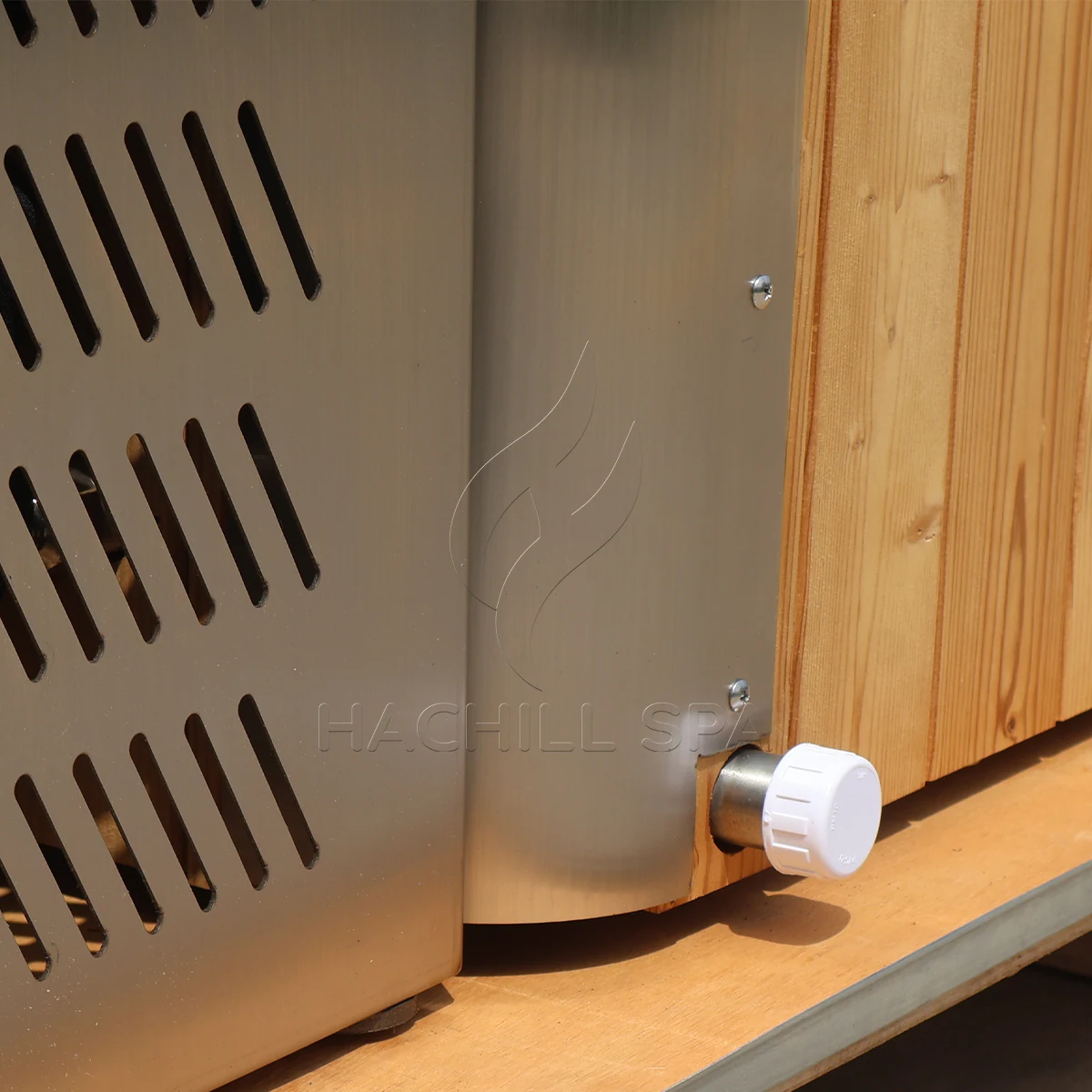
The register is configuration specific. A different water line, drain valve, hose, pump, filter location, cleaning method or room condition changes the event. Product photographs can identify visible interfaces, but cannot prove connection size, discharge rate, inclusion or site compatibility.
Convert Drain-Down into a Measured Discharge Event
Drainage design needs a rate-versus-time profile, not only tub volume. Begin with average observed discharge rate = measured discharged volume / measured elapsed time. This average can support comparison only when the valve position, hose, elevation, fittings, water level and downstream condition are recorded. Gravity flow normally changes as water level falls, so a single average does not prove the peak rate or every stage of emptying.
If a pump assists discharge, obtain the exact pump curve, approved operating point, controls and failure response. A nominal flow at zero head is not the installed flow. For gravity systems, record the vertical relationship, hose internal condition, bends, restrictions and whether the outlet can become submerged. Use a timed level or collected-volume series to show how rate changes instead of inventing a manufacturer discharge value.
| Record | Method | Condition held | Use |
|---|---|---|---|
| Starting water volume/level | Exact model data or measured basis | Operating configuration | Released volume boundary |
| Time-series volume or level | Calibrated collection/level method | Sampling interval | Rate profile |
| Valve/hose configuration | Photo and component record | Position, size and route | Repeatability |
| Elevation/downstream state | Survey and observed outlet | Same datum and destination | Gravity/head boundary |
| Average observed rate | Discharged volume / elapsed time | Declared interval | Receiving comparison only |
| Peak/abnormal behavior | Time-series observation | No uncontrolled release | Hold or redesign |
Freeze the Exact Product Drainage Boundary
Obtain the exact model and configuration drawing showing drain position, connection type, valve, union, low points and any included hose or adapter. Record drawing revision, units and connection datum. Separate product-supplied drainage from site-supplied pipework, floor drainage, waterproofing, backflow protection and disposal approval. A visible threaded fitting does not establish thread standard, nominal bore, permitted load or local compatibility.
Preserve valve operation, inspection and component-removal space after the tub is filled and furnished. A drain hidden behind fixed cladding may require moving a filled vessel for routine service. If a pumped or shared drain line is proposed, the qualified project team must review controls, cross-connections, backflow, pressure and failure modes; a blog cannot set those regulated interfaces.
| Interface | Supplier evidence | Site evidence | Hold condition |
|---|---|---|---|
| Drain outlet | Position, type and exact configuration | Compatible connection schedule | Generic photo or related model only |
| Valve/union | Approved operation and service need | Final access demonstration | Cannot inspect or isolate |
| Included hose/adapter | Order scope and material limits | Route and destination compatibility | Assumed inclusion |
| Equipment-service drains | Component manual/interface | Collection and access plan | Service releases uncontrolled |
| Product low points | Winter/service instruction | Site drain-down implementation | Trapped water path open |
Changes require interface review. If the tub, drain side, valve, hose, chiller or filter changes, identify affected layout, hydraulic, access, discharge and acceptance records. Do not transfer a connection value or drain procedure from a related model.
Verify the Entire Receiving Path under the Governing Event
The receiving path includes the product outlet, hose or pipe, fittings, air entry, cleanouts, trap where applicable, floor or receptor, branch drainage and final permitted destination. The controlling capacity may be far downstream from the visible product connection. Compare the measured or justified source event with the qualified drainage design at the same condition; do not declare capacity from grate size or pipe diameter alone.
A transparent screening relationship is receiving margin = verified receiving rate at test condition - governing source rate at the same condition. A positive arithmetic margin is not final approval: uncertainty, debris, partial blockage, simultaneous sources, trap condition, downstream surcharge and local design rules still apply. The qualified project designer determines pipe sizing and regulatory compliance.
| Checkpoint | Evidence | Condition | Acceptance question |
|---|---|---|---|
| Product outlet to hose | Exact connection and observed flow | Approved valve state | No leak, collapse or restriction |
| Hose/pipe route | Survey, slope and support record | Final installed route | No kink, high point or damage |
| Receptor/floor drain | Qualified design and flow test | Grate/trap in service state | Receives event without spread |
| Branch/downstream | Project drainage evidence | Simultaneous design state | No surcharge/backflow |
| Final destination | Local approval/operating procedure | Water condition declared | Discharge is permitted |
| Maintenance state | Inspection/cleaning record | Representative loaded condition | Capacity remains controlled |
Coordinate Floor Falls, Waterproofing and Slip Control as One System
A floor drain does not prove that the room is waterproof or that water reaches it. Coordinate finished floor levels, falls, thresholds, penetrations, membrane terminations, upstands, wall transitions, drains and cleanouts using the approved building system. The entry and exit zone must remain stable; a steep or irregular slope introduced to chase drainage can create another hazard.
For U.S. workplaces where OSHA rules apply, 29 CFR 1910.22(a)(2) requires workroom floors to be kept clean and, to the extent feasible, dry; where wet processes are used, drainage must be maintained and dry standing places provided to the extent feasible. This is a workplace walking-surface requirement, not a universal cold-plunge drainage design standard.
Acquire evidence through a dated field survey, approved waterproofing details, substrate and penetration inspection, flood or other specified system test, final fall survey and representative splash/cleaning observation. Record method, test limits, witnesses and deviations. Product installation should not conceal a membrane transition or prevent drain maintenance.
| Element | Responsible evidence | Field check | Release boundary |
|---|---|---|---|
| Finished falls | Approved levels/fall design | Survey and water observation | No uncontrolled ponding or dry-zone spread |
| Waterproofing | System details and compatible materials | Required inspection/test | Penetrations/terminations accepted |
| Thresholds/upstands | Coordinated architectural detail | As-built level and route check | Water not diverted to egress/dry zone |
| Drain/grate | Qualified drainage selection | Flush, access and task review | Stable walking/cleaning interface |
| Product penetrations | Exact connection/layout drawing | Sealing and movement check | No unapproved membrane breach |
| Maintenance access | Final furnished plan | Cleanout/grate demonstration | No hidden routine service point |
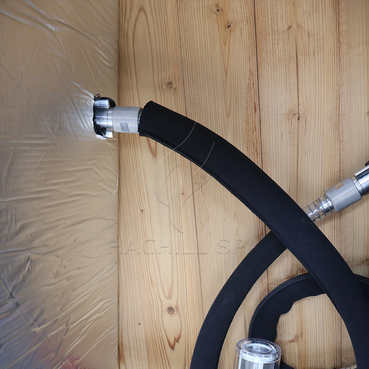
Document the wet-zone state before the tub blocks access. Photos alone are not a waterproofing test, but dated photographs tied to drawing revisions help resolve later disputes. The project record should distinguish building-waterproofing acceptance from product leak testing.
Separate Condensation from Leakage with Condition Data
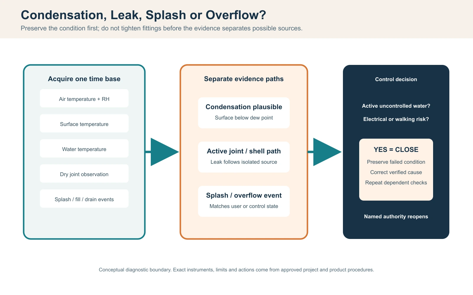
Condensation forms when a cold surface is below the dew point of surrounding air. For diagnosis, log room air temperature and relative humidity, surface temperature at named points, operating water temperature, ventilation state and time. Compare the surface and calculated or instrument-derived dew point using an identified method. This determines whether condensation is physically plausible; it does not rule out a simultaneous fitting leak.
Inspect insulation continuity, vapour-control direction, seams, valves, unions, pipe supports and penetrations. Cold bridges can concentrate water at a location remote from the source. The design response may involve approved closed-cell insulation, sealed vapour control, ventilation or dehumidification and a controlled condensate path. Material and thickness selection require the actual conditions and component instructions.
| Input / observation | Acquisition | Why it matters | Limitation |
|---|---|---|---|
| Air temperature/RH | Calibrated logger at declared location | Dew-point basis | One room value may miss microclimate |
| Surface temperature | Suitable contact/noncontact method | Condensation plausibility | Emissivity/location affect reading |
| Water temperature/time | Verified sensor time series | Cold-surface driver | Sensor placement documented |
| Joint/drain observation | Dry isolation and visual/tissue test | Active leak evidence | Concealed source may migrate |
| Insulation/vapour state | As-built inspection | Cold bridge and moisture path | Hidden areas remain open |
| Ventilation/door state | Operating log | Local humidity condition | Test must match accepted operation |
Control Cleaning and Equipment-Service Water
Routine work often creates the most frequent drainage events. Map filter removal, cartridge carrying, strainer opening, hose disconnection, sampling, tub cleaning and washdown. Record event frequency, expected water release, operator position, required tools, isolation state and route to the approved receptor. A service valve over an electrical component or a filter that must cross a guest route is an interface failure even if the full tub drain works.
Measure the task with the final access arrangement. Use service-water workload per period = sum(event frequency x observed collection/disposal time) + setup + records to expose staff burden; it is not a universal labor allowance. Separate hands-on time from required drain or contact time, and test an abnormal blocked or spilled condition.
| Task | Water source | Collection method | Stop / closure trigger |
|---|---|---|---|
| Filter removal | Housing and wet media | Tray/receptor and controlled carry | Water crosses electrical/user zone |
| Strainer/valve service | Trapped line water | Isolation plus local collection | Isolation not proven |
| Tub cleaning | Wash/rinse solution | Approved floor/receptor route | Chemistry or route not permitted |
| Sampling/testing | Small recurring samples | Named disposal point | Uncontrolled splash/storage |
| Hose disconnection | Residual water | Drain-down and cap procedure | Pressurized/trapped state unknown |
| Abnormal spill | Task failure | Isolation, containment and record | No competent response authority |
The operator owns routine procedure and records; the supplier provides exact product service instructions and boundaries; the project team provides the site receptor and wet-zone design. Staff should not improvise disposal into landscaping or a sink without confirming local compatibility and water chemistry.
Design Detection, Isolation and Containment for Abnormal Releases
Abnormal drainage planning asks how much water can escape before a competent person or automatic control stops the source. A screening input is response-release volume = verified source rate x measured detection-and-isolation time. Add any known stored volume released after isolation. This relationship exposes variables; it does not set a universal containment volume or replace qualified flood-risk design.
Test the response chain: detection, notification, access, valve or power isolation, user evacuation, protection of electrical equipment, containment, cleanup, cause investigation and reopening. Name the authority who can stop operation. Do not rely on a floor drain as the only protection if a blocked drain, hose failure or power loss can disable the intended path.
| Failure mode | Detection evidence | Isolation path | Reopening evidence |
|---|---|---|---|
| Drain hose disconnects | Visible/leak sensor/operator | Accessible valve and controlled stop | Connection cause corrected and retested |
| Tub overflow | Level/observation/alarm as equipped | Stop fill/circulation source | Control and procedure verified |
| Filter housing leak | Inspection/alarm/pressure change | Equipment isolation | Seal/assembly plus wet retest |
| Floor drain blocked | Ponding/inspection | Stop water source and close zone | Drain cleared and governing event repeated |
| Condensate overflow | Tray/route observation | Control cold source if required | Cause and disposal path verified |
| Electrical exposure | Visible water/protection event | Emergency qualified isolation | Qualified electrical release |
Stop opening for active uncontrolled leakage, unknown isolation, water reaching electrical equipment, unstable wet access, backed-up drainage, failed waterproofing acceptance or missing response authority. Reopening needs cause, correction and passing retest, not only a dry floor.
Confirm the Permitted Discharge Destination and Water Condition
Determine whether planned releases may enter sanitary drainage, a project receptor, controlled collection or another approved destination. Water treatment chemistry, disinfectant, cleaning products, temperature, volume, frequency and local sewer or environmental rules can change what is allowed. Outdoor discharge can create erosion, icing, foundation moisture, public-path hazards or impact neighboring property.
Obtain the decision from the qualified site team and relevant authority or utility where required. Record destination, applicable condition, maximum operational event, prohibited substances, operator procedure and evidence revision. A supplier can describe the equipment and water-treatment interface but cannot grant local disposal permission.
The discharge permission record should state the approved destination, allowed water condition, governing event volume and rate, timing restrictions, outdoor erosion or icing controls, evidence revision and named operator action. Reopen that record when the product, treatment chemistry, cleaning method, site route, season, utility rule or local requirement changes.
For public or commercial aquatic venues, reference frameworks can help the project team identify questions but do not establish universal cold-plunge requirements. The CDC Model Aquatic Health Code (MAHC) is voluntary guidance for aquatic venues open to the public and only has legal effect where a jurisdiction adopts it. The PHTA standards catalogue can help identify pool, spa and hot-tub standards that may be relevant, but applicability depends on the exact venue, product classification, adopted code and authority having jurisdiction.
Map Every Trapped Volume for Freeze Protection
Opening the tub’s low drain does not prove the system is empty. Water may remain in pumps, filters, heat exchangers, check valves, high loops, horizontal hoses, sensor pockets and site pipework. Obtain the exact system drain-down or winterization instruction and an as-built trapped-volume map. State whether the method uses gravity, disconnection, approved air purge, heat, circulation or other controls.
Record ambient exposure, power-loss case, duration, access, responsible role and verification method. Fixed wiring, internal refrigeration work and pressurized purging require qualified personnel and exact manufacturer limits. Do not prescribe one winter method across all models and site systems.
| Component / zone | Potential retained water | Approved action | Verification |
|---|---|---|---|
| Tub low point | Shell/base connection | Exact drain procedure | Observed empty state |
| Pump/filter | Housings and internal passages | Manual-specific isolation/drain | Inspection or documented method |
| Heat exchanger/chiller | Small protected passages | Exact equipment procedure | Qualified service record |
| Check valves/high loops | Trapped sections | As-built disconnection/drain plan | Route-by-route confirmation |
| Site pipe/hose | Sags and horizontal runs | Approved slope/remove/purge method | Final configuration check |
| Power-loss state | Protection may stop | Emergency response plan | Drill and escalation evidence |
Grade Drainage Evidence and Control Revisions
For internal project control, evidence can be graded by how closely it matches the exact installation; this A–D framework is a documentation method used in this guide, not an industry or regulatory grading standard. Grade A is approved exact-configuration evidence or witnessed project acceptance at the declared event. Grade B is a controlled exact-model or site test with a defined condition gap. Grade C is related-model, declared or incomplete-method evidence. Grade D is an assumption, photograph or marketing statement. Record model, route, method, instruments, condition, witness, date, raw result, revision and limitation.
| Grade | Example | Permitted use | Next action |
|---|---|---|---|
| A | Approved exact drawing or witnessed governing-event test | Close stated interface within limits | Maintain change control |
| B | Controlled exact-model/site test with condition gap | Conditional design input | Reconcile gap |
| C | Supplier declaration, related model or incomplete route | Question/shortlist only | Obtain exact evidence |
| D | Photo, assumption or generic claim | Cannot release work | Measure, test or leave open |
Preserve superseded evidence. When a valve, hose, drain, floor level, membrane penetration, cleaning product, operating water level or discharge destination changes, identify affected drawings, calculations, procedures and tests. A prior pass remains historical evidence; it cannot be silently relabeled as proof of the changed state.
Assign Product, Building, Installation and Operating Responsibility
The supplier owns exact product connection, included scope and model-specific service or winter instructions. The qualified project team owns building drainage, waterproofing, floor falls, structural/electrical interfaces, permitted destination and local compliance. The installer records the approved as-built connection and wet-zone work. The operator owns routine drain-down, cleaning, inspection, closure and records. Named technical authorities own specialist diagnosis and reopening.
| Interface | Accountable owner | Required evidence | Release authority |
|---|---|---|---|
| Product outlet/valve | Supplier | Exact drawing, scope and instruction | Buyer technical authority |
| Building drain/waterproofing | Qualified project team | Approved design and tests | Project/AHJ as applicable |
| As-built route | Installer | Photos, checklist and deviations | Project technical authority |
| Discharge permission | Site owner/project team | Utility/AHJ/project record | Named local authority |
| Routine operation | Operator | Drain/clean/inspect/closure logs | Duty manager |
| Fault and retest | Named qualified parties | Cause, correction and controlled result | Technical/operating release |
A matrix is useful only when each owner accepts the output and due stage. Replace “by others” with a named party. HACHILL can support exact product-interface clarification and configuration evidence when the selected model and project brief are supplied; it does not replace local drainage, waterproofing or regulated design.
Accept Documents, Construction, Dry Access, Wet Events and Reopening Separately
Document acceptance closes exact model, connection, route, destination, responsibility and open values. Construction acceptance closes drainage and waterproofing work before concealment. Dry access confirms valve, union, cleanout, grate and component removal. Wet acceptance tests routine service, representative splash/cleaning and the governing controlled drain event. Abnormal-response acceptance demonstrates detection, isolation, containment and authority.
Define test water condition, volume, valve state, simultaneous sources, instruments, sample interval, witnesses, pass/hold criteria and cleanup before filling. For a dispute, preserve the original requirement, raw readings, photos, route state, failed event and downstream observations. Record suspected cause and corrective change. Retest the controlled change while retaining valid conditions, and repeat dependent waterproofing, drainage, electrical-exposure or operating checks.
| Gate | Minimum evidence | Hold example | Release basis |
|---|---|---|---|
| Documents | Exact revisions, route, destination and owner | Conflicting/related-model data | Approved controlled pack |
| Construction | Pre-concealment waterproofing/drain evidence | Open penetration or failed test | Qualified acceptance |
| Dry access | Valve, union, grate and cleanout demonstration | Routine point inaccessible | Corrected layout check |
| Wet events | Service, splash and governing drain time series | Ponding, surcharge or leakage | Passing declared-event test |
| Abnormal response | Detection through isolation and record drill | No stop/reopen authority | Signed response acceptance |
| Controlled retest | Original fail, cause, change and dependencies | Failure overwritten/method changed | Authorized evidence review |
Do not overwrite failed data with the passing retest. A dry floor after cleanup is not a passed drainage test. Opening remains held while active leakage, uncontrolled ponding, failed waterproofing, unknown discharge permission, unsafe wet access, electrical exposure, freeze-risk gap or missing competent authority remains open.
Issue a Normalized Drainage and Wet-Zone RFQ
Send the exact tub and system configuration, operating water level or volume basis, drain drawing, intended drain-down interval, gravity or pump method, room and route survey, receiving drainage evidence, waterproofing system, cleaning/service tasks, indoor air conditions, discharge destination, freeze exposure, responsibility matrix, evidence grade and acceptance schedule.
| Package | Buyer / project supplies | Supplier returns | Close before |
|---|---|---|---|
| Product interface | Selected model/configuration | Exact drain/valve/scope data | Layout freeze |
| Source events | Use, cleaning and abnormal cases | Applicable product limits | Drain design |
| Site route | Levels, receptor and destination | Connection/access requirements | Site penetrations |
| Condensation/freeze | Air/climate and shutdown case | Exact insulation/service boundaries | Order/site freeze |
| Evidence/compliance | Destination and required grade | Documents without certification overclaim | Dispatch |
| Acceptance/support | Tests, witnesses and records | Product checks and deviation response | Opening |
Ask every bidder to identify exact values, included and excluded scope, declared conditions, deviations and open items. Keep an unsupported number open with an owner and due date. Compare price only after the discharge event and scope are normalized.
Frequently Asked Questions
Does every laydown cold plunge installation need a floor drain?
Not every jurisdiction or room uses the same solution, but the project must control full drain-down, service water, splash, cleaning, condensation and abnormal leakage. A qualified site designer should approve the collection, waterproofing and permitted discharge route for the exact installation. A product drain fitting does not replace building drainage or wet-zone design.
How do you check whether a floor drain can handle cold plunge drain-down?
Record the verified water volume, valve and hose configuration, elevation and a controlled rate-versus-time drain test. Compare the governing source event with the qualified receiving path, including grate, trap, branch and downstream condition. Pipe or grate size alone is insufficient, and simultaneous splash or cleaning sources must be included when the operating procedure allows them.
Why does water appear under a stainless steel cold plunge?
Possible sources include a drain or fitting leak, splash, overflow and condensation where a surface is below room dew point. Dry and isolate the area before changing fittings. Log air temperature, humidity, surface and water temperatures, then inspect accessible joints and insulation. More than one source can occur at the same time.
Can cold plunge water be discharged outdoors?
Only when the exact route, water chemistry, volume, erosion, icing, foundation and local disposal requirements permit it. Do not route water across public paths, neighboring property or an uncontrolled landscape area. The site owner and qualified project team should obtain any required utility or authority approval and give operators a written procedure.
How should a laydown cold plunge be drained for freezing weather?
Use the exact tub, pump, filter, chiller, heat-exchanger and site-pipe winterization instructions. Opening one tub drain may leave water in check valves, high loops, housings and small passages. Map every trapped zone, assign qualified responsibility and record verification. Generic drain-down advice cannot prove freeze protection for a specific system.
Related HACHILL Resources
Laydown cold plunge range
Review the verified product-family destination after drainage inputs are controlled.
Cold plunge water-care guide
Continue into routine water-management questions.
Commercial cold plunge solutions
Coordinate the drainage interface with the commercial system scope.
Installation support
Review verified support scope without transferring local design responsibility.
Request a project quotation
Submit the normalized drainage and wet-zone brief.
Reference Basis and Limits
- CDC Model Aquatic Health Code (MAHC) — current voluntary guidance for aquatic venues open to the public; use only where the project and local jurisdiction make it applicable.
- PHTA standards catalogue — index of ANSI/PHTA/ICC pool, spa and hot-tub standards; relevance depends on product/venue classification and jurisdictional adoption.
- OSHA 29 CFR 1910.22 — U.S. workplace walking-working-surface requirements, including drainage and dry-standing provisions where wet processes are used; not a cold-plunge sizing standard.
Technical and safety boundary: This article does not claim a HACHILL connection size, discharge rate, waterproofing performance, freeze protection, certification, site approval or medical benefit. Exact product manuals, approved drawings, qualified drainage and waterproofing design, licensed trades, trained operators and destination requirements take priority over general web guidance.