Quick answer: size the room before you size the heater
The correct sauna heater size starts with the measured internal hot-room volume, then adjusts that volume using the selected heater manufacturer's current method for glass, masonry, log walls or other poorly insulated surfaces. The result is an effective room volume, not an automatic kW answer. A buyer must still confirm that the exact heater model is approved for that effective-volume range and that its controls, sensor location, clearances, electrical supply, ventilation interface and destination-market requirements fit the project.
Do not select a heater from seat count, external cabin dimensions or a universal “kW per cubic metre” shortcut. Those methods can miss ceiling height, full-height glazing, outdoor exposure, ventilation load, repeated door opening and commercial recovery duty. Before requesting a quotation, prepare five controlled inputs: a dimensioned internal survey, an uninsulated-surface schedule, the operating and climate basis, the ventilation concept, and the available electrical supply. Fixed wiring, protection, clearances and code compliance must be reviewed by the heater instructions, qualified local professionals and the authority having jurisdiction.
A left-to-right technical decision chain showing internal room dimensions, glazing and exposed surfaces, operating duty, manufacturer model check, electrical and ventilation coordination, then commissioning evidence.
Planned file: sauna-heater-sizing-input-decision-chain.webp | 1200 x 900 WebPDefine the design basis before using a calculator
A calculator is only as reliable as the assumptions entered into it. Two rooms with identical length, width and height can impose different duties on a heater because one is an insulated indoor residential room used once in the evening, while the other is an outdoor commercial room with a glass front and frequent door cycling. The geometry is the same; the design basis is not.
Freeze the design basis before the heater shortlist is approved. “Freeze” does not mean every project detail is final. It means each known input has a dated source, each unknown is visible, and the calculation states which revision it used. At minimum, record:
| Design-basis input | Pourquoi cela change la décision | Evidence to retain |
|---|---|---|
| Intended venue and users | Residential and commercial rooms can have different warm-up, recovery, guarding and operating expectations | Project brief and operating concept |
| Internal or external installation | Outdoor temperature, wind exposure and envelope transitions can increase losses | Site plan, climate basis and wall/roof build-up |
| Intended operating pattern | One warm-up per day differs from repeated door cycling and long occupied periods | Duty schedule and expected session turnover |
| Room target and warm-up objective | A target without defined starting conditions cannot become an acceptance criterion | Owner's requirement with stated conditions |
| Wall, ceiling, floor and door construction | Insulation, thermal bridges and exposed mass affect transient and steady load | Approved section drawings and finish schedule |
| Glazing and other uninsulated surfaces | These surfaces often require a manufacturer-defined correction | Dimensioned elevation and surface schedule |
| Ventilation concept | Supply-air temperature and airflow affect heat loss, stratification and sensor response | Ventilation design and control state |
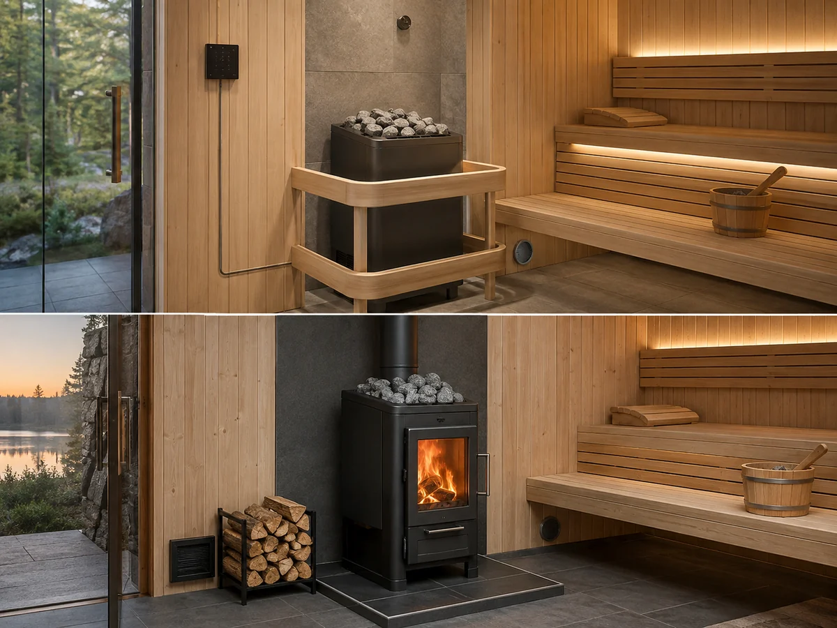
| Heater route | Electric traditional, wood-burning and infrared systems are not interchangeable sizing problems | Approved system definition |
| Alimentation électrique | Voltage, phase, current capacity and protection can constrain the model shortlist | Site electrical schedule reviewed locally |
| Destination market | Installation, documentation and conformity routes vary by jurisdiction | Project compliance matrix |
Keep assumptions that have not been approved in an open-item register. For example, if the glazing width is still under design, the calculation should show the current provisional area and identify the designer as the owner. It should not silently convert a provisional drawing into a final heater order.
For an HACHILL sauna project, this design-basis record also separates room-level coordination from model-level facts. HACHILL can review the sauna enclosure, layout and project inputs against the proposed configuration, but the final heater selection still depends on the exact approved heater data, the project electrical design and local requirements.
Measure net internal room volume correctly
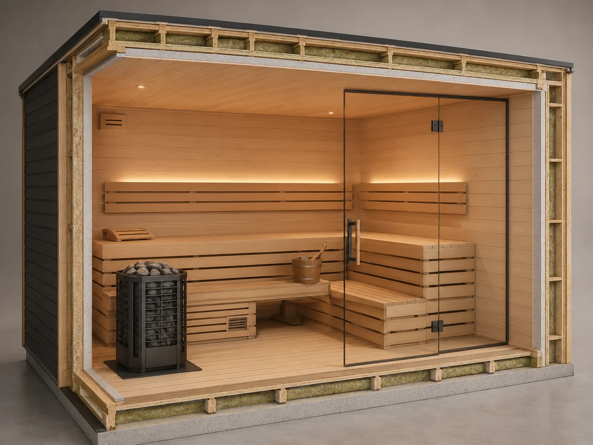
The starting volume is the air space inside the finished hot room. External cabin dimensions include wall build-up, insulation, service cavities and cladding, so they can overstate the heated volume. A marketing capacity such as “four person” does not define the volume at all.
For a rectangular room:
V_net = L_internal x W_internal x H_internal
Use one unit system throughout the worksheet. If dimensions are measured in metres, the result is cubic metres. If dimensions are measured in feet, the result is cubic feet. Convert only once, document the conversion and keep the original measurements. Repeated rounding can move a room close to a model boundary without anyone noticing.
Rectangular rooms
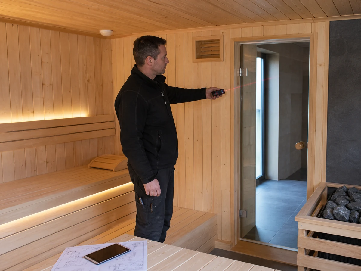
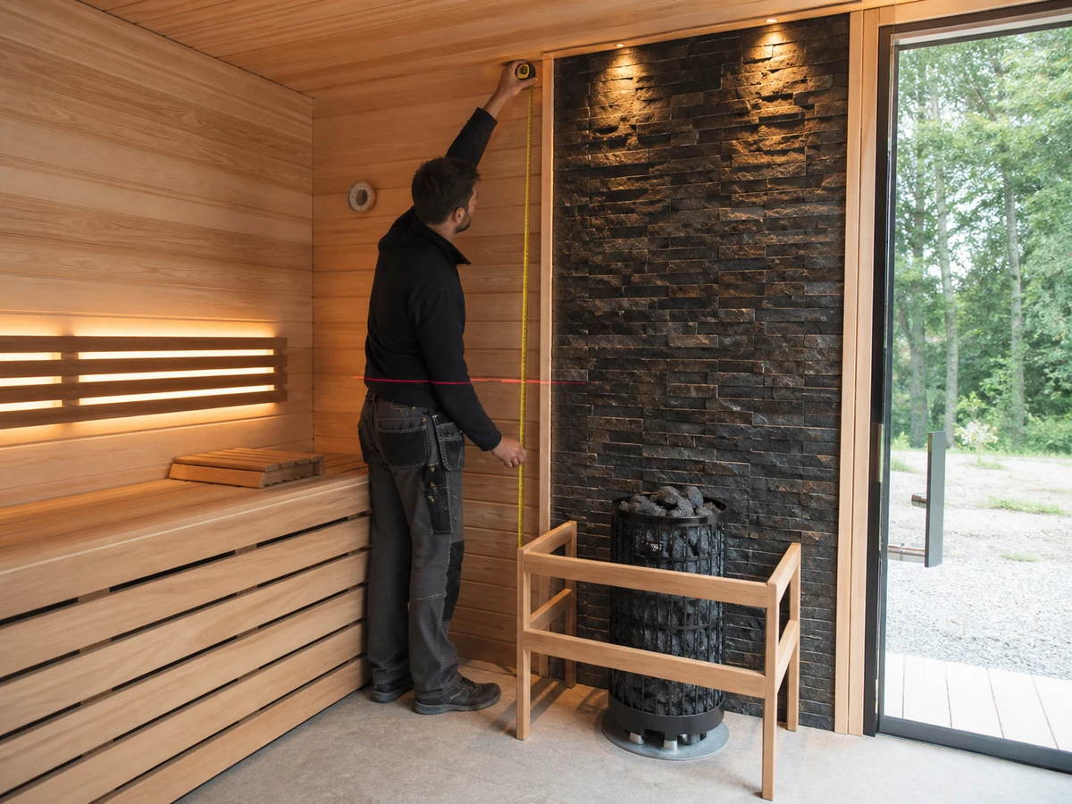
Measure finished internal length, width and height. Do not copy a nominal module size unless the approved drawing explicitly states that it is the clear internal dimension. Record where each measurement was taken and whether finishes, benches, heater guards or service components were installed at the time.
Benches normally displace only a small part of the air volume, but that does not justify subtracting them from the room calculation unless the selected manufacturer's sizing instructions explicitly require it. The heater manufacturer defines the permitted calculation method for its model range.
Irregular rooms and sloped ceilings
Divide an irregular room into simple solids and add their volumes:
V_net = V_1 + V_2 + ... + V_n
For a sloped ceiling, separate the rectangular lower part from the wedge or use an average height only when the geometry supports it. Attach a sketch with segment labels so another reviewer can reproduce the total. If a ceiling pocket, soffit or void communicates openly with the hot room, do not ignore it simply because it is above the normal occupied zone.
Survey evidence
The measurement record should contain the drawing revision, survey date, instrument or method, units, measurer, reviewer and photographs or marked-up drawings. If site measurements conflict with approved drawings, the conflict is a design issue, not a rounding decision. Resolve it before final heater selection.
A frequent receiving error occurs when a prefabricated sauna is quoted from external dimensions and the heater is selected before the final internal build-up is confirmed. The apparent error may not become visible until the room is installed. Recording both external and internal dimensions in separate fields prevents the sales dimension from being reused as a thermal input.
Convert glass and uninsulated surfaces into effective volume
Net air volume is the beginning of the sizing method, not the end. Glass doors and walls, exposed masonry, solid log surfaces and other poorly insulated areas can raise the heater duty because they lose more heat or absorb more energy than a well-insulated timber assembly. Heater manufacturers commonly address this through an equivalent- or effective-volume correction, but the coefficient and eligible surfaces are manufacturer-specific.
A controlled worksheet can express the method as:
V_effective = V_net + sum(A_i x C_i)
where:
V_effectiveis the volume used to check the heater manufacturer's permitted room range;V_netis the measured finished internal volume;A_iis the measured area of each correction surface;C_iis the correction factor taken from the current sizing instructions for the selected heater route.
Do not enter a remembered factor from a different brand, product generation or market. The worksheet must cite the document title, revision or publication date, page and model family that supplied each C_i. If the manufacturer uses a calculator rather than a stated coefficient, save the complete input record and result, then verify that the calculator applies to the exact shortlisted model.
| Surface register field | Required entry | Control rule |
|---|---|---|
| Surface ID | G1, G2, M1, L1, etc. | Match the elevation drawing |
| Construction | Glass, masonry, solid log or other | Do not infer from appearance alone |
| Clear width and height | Measured dimensions | Exclude frames only if the manufacturer method says so |
| Zone | Width x height | State units and rounding |
| Correction rule | Manufacturer document or calculator | Current selected model family only |
| Equivalent-volume addition | Area x approved factor or tool result | Do not substitute an industry shortcut |
| Status | Confirmed / provisional / excluded with reason | Provisional surfaces remain open items |
Illustrative calculation that stops at the correct boundary
Consider a room with finished internal dimensions of 2.40 m x 2.10 m x 2.20 m:
V_net = 2.40 x 2.10 x 2.20 = 11.088 m3
The room also has a 1.40 m x 2.00 m glass area and a 1.20 m x 2.20 m exposed masonry area:
A_glass = 1.40 x 2.00 = 2.80 m2
A_masonry = 1.20 x 2.20 = 2.64 m2
If the selected heater manufacturer specifies correction factors C_glass et C_masonry, the controlled result is:
V_effective = 11.088 + (2.80 x C_glass) + (2.64 x C_masonry)
The calculation intentionally stops here. Without the current manufacturer's factors and permitted model ranges, assigning a kW value would create false precision. Once those controlled inputs are available, record the calculated effective volume without excessive rounding and compare it with the exact model table. If the result sits close to a model boundary, review the unresolved loads and seek written manufacturer guidance rather than automatically selecting up or down.
A dimensioned cutaway of a traditional sauna room with finished internal length, width and height plus surface IDs G1 for glass and M1 for masonry; no numerical coefficient or heater kW recommendation.
Planned file: sauna-room-effective-volume-glass-masonry-survey.webp | 1200 x 900 WebPRegister the loads a room-volume calculator can miss
Equivalent volume is a practical product-selection method, but it is not a complete dynamic thermal model. A project can still underperform if ventilation, thermal mass, climate, door cycling or control placement differs from the assumptions behind a standard calculator.
The engineering load path can be described conceptually as:
Required heater duty = envelope losses + ventilation losses + warm-up energy + opening/recovery load + project margin
For a detailed design, envelope heat transfer follows the relationship:
Q_envelope = sum(U_i x A_i x DeltaT_i)
Ventilation heat loss follows:
Q_ventilation = air density x air heat capacity x airflow x temperature rise
Warm-up energy includes the air, lining, benches, stones and other thermal mass:
E_warm-up = sum(m_j x c_j x DeltaT_j)
These formulas explain why a volume-only shortcut can fail, but this article does not supply universal U, airflow, material heat-capacity or design-temperature values. Those inputs must come from the approved construction, ventilation design, component information and project conditions. The heater's electrical input rating is also not automatically equal to useful heat delivered to the occupied room throughout every phase of operation.
Use a load register to decide whether each non-geometric condition is already covered by the manufacturer's sizing method, requires a separate calculation, or needs written review:
| Load condition | What can go wrong | How to verify | Owner / disposition |
|---|---|---|---|
| Outdoor wall or roof exposure | Standard indoor assumptions understate loss | Review climate basis and envelope sections | Designer; quantify or obtain manufacturer review |
| Thermal bridges or weak interfaces | Local losses and condensation risk occur at joints | Inspect wall/roof/base details | Enclosure designer and manufacturer |
| Ventilation airflow | Excess or misdirected air increases loss or temperature stratification | Review design airflow, inlet and outlet positions | Ventilation designer / installer |
| Cold supply air | Heat loss rises even when airflow is unchanged | Record source and design temperature | Mechanical designer |
| High stone or masonry mass | Warm-up time increases although steady operation may be acceptable | Confirm exact heater/stone arrangement and room mass | Heater data plus designer review |
| Frequent door openings | Empty-room test does not represent service | Define openings or user turnover for test basis | Operator / project manager |
| Oversized or poorly sealed door | Infiltration and repeated recovery load increase | Inspect dimensions, seals and closure | Room manufacturer / installer |
| Sensor location | Heater cycles from a local hot spot while occupied zone remains cool | Verify exact instructions and measured map | Heater supplier / qualified installer |
| Changed ceiling or glazing | Original model range no longer matches the room | Recalculate from approved revision | Designer / buyer change control |
A commercial project should state whether the heater is being selected for morning warm-up only, continuous occupied operation, repeated recovery after door openings, or all three. “Commercial use” is not a numerical input by itself. The operator must describe the intended user flow and the project team must translate that into measurable test conditions.
Shortlist a heater from approved manufacturer data
After calculating effective volume and reviewing non-geometric loads, use the exact manufacturer's current data to create a shortlist. Do not reverse the process by choosing a preferred heater appearance first and modifying the room calculation until it fits.
Check the following items together:
| Model-verification item | Pourquoi c'est important | Evidence required before approval |
|---|---|---|
| Permitted room-volume range | Establishes whether the effective volume is within the model's intended range | Current model data sheet or selection tool |
| Heater type and installation orientation | Wall, floor and other arrangements change layout and instructions | Exact model installation manual |
| Rated electrical characteristics | kW alone does not define voltage, phase, current or controls | Nameplate schedule and current technical data |
| Control architecture | Integral and separate controls affect wiring and sensor location | Control and heater compatibility record |
| Sensor type and position | Incorrect placement can cause premature cycling or unsafe operation | Manufacturer installation instructions |
| Clearances and heater guard | The room layout must maintain required distances and prevent contact where applicable | Dimensioned coordination drawing |
| Stone specification and loading | Incorrect type, size, quantity or placement can alter airflow and performance | Exact heater instructions |
| Ventilation compatibility | Airflow can affect heater cooling, sensor response and room distribution | Heater instructions plus ventilation design |
| Service and replacement access | A technically sized heater can still be unmaintainable | Coordinated layout and access plan |
| Portée documentaire du marché de destination | Electrical and conformity evidence is model-, configuration- and market-specific | Controlled document matrix |
The correct model is not necessarily the one with the highest rating. Oversizing can introduce larger electrical infrastructure, different minimum room-volume limits, control behaviour or uncomfortable cycling. Undersizing can lead to long warm-up, poor recovery or continuous operation without achieving the project condition. The selection should sit within the manufacturer's permitted range and be reviewed against the unresolved load register.
IEC 60335-2-53 addresses safety requirements for sauna heating appliances within its stated scope, while IEC 60364-7-703 addresses low-voltage electrical installations in rooms and cabins containing sauna heaters within its scope. These references help define the safety review landscape. Standards context does not prove that an unnamed heater or every HACHILL configuration has been tested or certified to either standard. Confirm the applicable edition, national adoption, exact model evidence and local requirements for the destination market.
Coordinate heater sizing with electrical, ventilation and layout design
A heater shortlist is not releasable until the site can support it. Treat electrical, ventilation and room-layout coordination as parallel design checks, not installation details to solve after delivery.
Electrical interface
Record voltage, frequency, phase, available capacity, control location and the local protection/isolating concept. The qualified electrical designer or installer must size conductors, protective devices, isolation, grounding/bonding and routing in accordance with the exact equipment instructions and local rules. This guide does not provide fixed-wire instructions or universal breaker and cable sizes.
If the desired model requires a supply the project does not have, the team must choose among a documented supply upgrade, a different approved heater route or a room/design revision. Do not change phase, control package or heater configuration in the purchase order without repeating the technical and document review.
Ventilation and sensor interface
Ventilation must support air quality and room distribution without creating an uncontrolled heat-loss path or misleading the control sensor. The heater manufacturer and room ventilation design may specify relationships among heater position, supply inlet, exhaust or return point and sensor. Confirm those relationships on one coordinated drawing.
A sensor placed too close to a hot air plume may stop heating while the upper-bench occupant zone remains below the intended condition. A sensor shielded or installed outside its approved location can create the opposite risk. Moving a sensor to “improve performance” without the manufacturer's instructions and qualified review is not an acceptable commissioning adjustment.
Layout, clearances and service access
Verify heater clearances to walls, benches, glazing, guards and other surfaces using the exact installation manual. Show door swing, user circulation, heater guard and maintenance access. A floor-standing heater that fits the thermal calculation may block the route between the door and benches; a wall-mounted unit may conflict with glazing, framing or cable routing. These are selection failures even if the kW value is correct.
For broader enclosure, insulation and ventilation planning, use a separate construction guide after the room-level thermal assumptions are frozen. The current page remains responsible only for the heater-sizing decision and its interfaces.
Use a traceable calculation worksheet
A useful sizing worksheet is a controlled project record, not a calculator screenshot with no inputs. It should let a second reviewer reproduce the result and identify every provisional assumption.
| Worksheet section | Required fields |
|---|---|
| Document control | Project, room ID, revision, author, reviewer, date, status |
| Geometry | Finished internal length, width, height, segments, units, net volume |
| Surface schedule | IDs, construction, dimensions, areas, correction sources and status |
| Effective volume | Formula, factors, factor sources, result and rounding rule |
| Design basis | Venue, duty, target basis, starting condition, climate and indoor/outdoor status |
| Load register | Envelope, ventilation, thermal mass, openings, sensor/control and open issues |
| Heater shortlist | Model, current data revision, permitted room range, control and sensor route |
| Site utilities | Voltage, frequency, phase, available capacity and local review status |
| Coordination | Clearances, guard, ventilation, door, service access and drawing references |
| Preuve | Manual, data sheet, calculations, approvals and destination-market document status |
| Approbation | Responsible parties, deviations, expiry/review trigger and purchase-release status |
Use distinct status terms:
- Confirmed: supported by a current controlled record.
- Provisional: suitable for preliminary review but not purchase release.
- Not applicable: excluded with a stated reason and reviewer.
- Open: missing or disputed; owner and due date assigned.
Do not label a field “confirmed” because it appears in an email thread. Transfer it into the controlled worksheet or approved project document, identify the source and obtain the required approval.
The worksheet must also define recalculation triggers. Typical triggers include a changed internal dimension, additional glazing, altered insulation, different heater model, control change, revised electrical supply, modified ventilation, outdoor relocation or a new commercial duty schedule. A heater selected against revision A should not survive into revision C by inertia.
Commission the room instead of accepting a nameplate
Commissioning asks whether the installed room and heater perform under the agreed conditions. It does not replace product safety tests, local inspection or the manufacturer's commissioning instructions. The project team should agree the test method before purchase order release, particularly when warm-up or recovery performance is commercially important.
Pre-test checks
Before energising the heater, the responsible qualified parties should verify:
- installed heater, control, sensor and stone arrangement match the approved configuration;
- clearances, guards and service access match the approved drawing and instructions;
- electrical supply and protective measures have been checked and recorded by the qualified local party;
- ventilation is complete and set to the agreed test condition;
- door, seals, glazing, lining and visible penetrations are complete;
- the room is dry and free from packaging, tools and combustible debris;
- test instruments are identified, suitable and within their required calibration or verification status;
- stop conditions and responsible test leader are known.
Do not proceed through burning odour beyond expected initial conditioning, visible smoke, arcing, repeated protective-device operation, damaged controls, loose components or any condition the manufacturer or local professional identifies as unsafe. Isolate the equipment and escalate to the responsible qualified party.
Temperature measurement map
Use a drawing to identify every measurement point. A practical project map may include:
A: ambient condition outside the room;U: upper-bench occupant zone;F: lower-bench or foot zone;R: return/exhaust-side reference;C: controller display or control-sensor reference;- optional surface or adjacent-space points where the project risk assessment requires them.
Record each point's horizontal location, height above finished floor, distance from heater or openings, instrument ID and installation method. Do not place a measurement point where it receives direct radiant or convective influence unless that is the defined purpose. The control sensor itself must remain in the manufacturer-approved location; the measurement map observes the system and does not authorise sensor relocation.
Time-series test record
| Enregistrer | What to capture |
|---|---|
| Initial conditions | Room points, outdoor/adjacent condition, heater and room condition |
| Configuration | Heater, control, sensor, stones, ventilation and door state |
| Electrical confirmation | Supply/configuration check by the qualified responsible party |
| Time series | Start time and readings at the agreed interval for all points |
| Events | Door openings, control changes, alarms, interruptions and observations |
| End point | Contract-defined target or test stop condition |
| Result | Pass, fail, conditional pass or invalid test |
| Suivi | Deviation owner, corrective action and retest requirement |
Acceptance limits must be written for the specific project. This guide does not impose a universal warm-up time, temperature or vertical uniformity. A result is invalid if the starting condition, ventilation state, door sequence, supply or instrument locations differ materially from the approved method. Repeat the test after returning the system to the defined baseline.
A plan-and-section technical illustration locating A, U, F, R and C measurement points relative to the heater, benches, inlet, exhaust and controller; arrows show airflow without implying a universal vent layout.
Planned file: sauna-heater-commissioning-temperature-measurement-map.webp | 1200 x 900 WebPAllocate responsibility before purchase order release
Sizing failures often originate at the interfaces between organisations. A room supplier may assume the electrical designer selected the heater; the electrical designer may assume the supplier included glazing corrections; the operator may introduce a high-throughput duty that was never in the project brief. A responsibility matrix turns these assumptions into named deliverables.
| Deliverable | Buyer / designer | Sauna room supplier | Heater supplier | Installateur / professionnel local | Exploitant |
|---|---|---|---|---|---|
| Approved internal geometry | A/R | C | I | C | I |
| Surface and insulation schedule | A/R | C/R for supplied assembly | I | C | I |
| Effective-volume calculation | A | C | R for model-specific method | C | I |
| Exact heater model data | I | C | A/R | C | I |
| Electrical design and compliance | A | I | C for equipment data | R | I |
| Ventilation design | A/R | C | C for heater interface | C/R as contracted | I |
| Clearances and coordinated layout | A | C | C for instructions | R for installed work | I |
| Operating duty definition | A | C | C | I | R |
| Commissioning method | A | C | C | R as contracted | C/R |
| Acceptance and closure | A | C | C | R for installed scope | C |
Legend: A accountable, R responsible, C consulted, I informed. The project contract may allocate roles differently. The matrix must be adapted and approved; it is not a substitute for contractual responsibility or local law.
For HACHILL-supplied sauna enclosures or project packages, confirm exactly which room, heater-interface, document and coordination deliverables are included in the approved quotation. Do not infer that HACHILL owns local electrical design, permits, final fixed wiring or authority approval unless the contract expressly assigns that scope.
Rank evidence before resolving a disagreement
Not all evidence has equal authority. Use this hierarchy when a calculator, drawing, brochure and field result disagree:
- Applicable law, authority decisions and approved local design for the project jurisdiction.
- Exact current heater model data and installation instructions, plus verified model-specific conformity documents where required.
- Approved project drawings and schedules for room construction, ventilation, electrical supply and operating basis.
- Controlled sizing worksheet and engineering review with cited inputs, assumptions and revisions.
- Commissioning and inspection records captured under an approved method.
- Photographs, catalogues, sales pages and correspondence as supporting context only.
A showroom photograph cannot prove a clearance. A generic certificate cannot prove that the ordered model and market are covered. A calculator result cannot override the exact installation manual. A field complaint without recorded starting conditions cannot by itself prove undersizing.
Resolve acceptance failures and sizing disputes with evidence
When the room warms slowly, cycles unexpectedly or shows uneven temperature, do not begin by replacing the heater. Preserve the baseline and determine whether the deviation arises from sizing, installation, supply, controls, ventilation, enclosure, operation or the test itself.
Use a controlled closure sequence:
- Record the deviation. State the approved criterion, observed result, date, configuration, conditions and evidence.
- Make the system safe. Stop use if any unsafe symptom exists; qualified personnel decide isolation and access.
- Validate the test. Confirm instruments, measurement locations, start condition, ventilation, door events and supply.
- Compare the as-built condition. Check room dimensions, surfaces, insulation interfaces, heater/control/sensor configuration and approved revisions.
- Assign the likely cause and owner. Separate calculation error, unapproved change, installation defect, equipment issue, operating mismatch and invalid test.
- Approve corrective action. Do not improvise sensor relocation, ventilation blocking, clearance reduction or electrical changes.
- Retest from the agreed baseline. Use the same method unless a controlled revision is approved.
- Close the record. Attach the result, approvals, residual limitations and updated drawings or instructions.
| Dispute question | Minimum evidence | Decision owner |
|---|---|---|
| Was the heater selected for the approved room? | Approved geometry, surface schedule, worksheet and model table | Project technical authority |
| Did the room change after selection? | Drawing revisions, change log and as-built survey | Buyer / designer |
| Is the supply correct? | Qualified electrical inspection and equipment data | Local electrical professional |
| Is control behaviour credible? | Sensor location, control configuration and time-series record | Heater supplier plus qualified installer |
| Is ventilation affecting the result? | Ventilation design, setpoints and test state | Mechanical designer / installer |
| Is the test valid? | Approved method, instrument record, event log and conditions | Commissioning lead |
| Who pays for retest or correction? | Contract, approved scope, cause record and change responsibility | Contracting parties |
This process matters because a disputed warm-up time can produce several incompatible claims: “heater too small,” “room poorly insulated,” “supply voltage wrong,” “sensor badly placed,” or “door opened too often.” Without controlled evidence, each party can repeat its preferred explanation and no one can close the issue.
Field scenarios that expose common sizing mistakes
Composite project scenario 1: full-height glass was omitted
Problème : A heater was shortlisted from net air volume, but the final room included a full-height glass door and adjacent glass panel. The installed room took longer to reach the project condition than the buyer expected.
Cause probable : The glazing elevation changed after the preliminary calculation, and no one repeated the manufacturer's effective-volume correction. The purchase record contained the old room volume but no surface schedule.
Comment vérifier : Compare the approved and as-built glazing dimensions, reconstruct V_net, obtain the correct model-specific correction rule, and compare the resulting effective volume with the heater's current permitted range. Validate the test conditions before assigning cause.
Correction / prevention: Put glazing area and revision status in the sizing worksheet, make glazing change a formal recalculation trigger, and require technical release after architectural changes. Corrective equipment or room changes must follow manufacturer, project and local professional review.
Composite project scenario 2: external cabin dimensions entered into a calculator
Problème : A dealer entered a catalogue cabin size into a heater calculator. Later drawings showed a different finished internal height and several service voids.
Cause probable : The catalogue dimension described transport or exterior geometry, while the calculator required finished internal dimensions. No field identified the dimension source.
Comment vérifier : Measure or extract the clear internal length, width and height from the approved drawing; compare them with the original input; identify wall and ceiling build-up; recalculate net volume with stated units.
Correction / prevention: Maintain separate external, delivery and internal dimensions. Require a marked-up survey or approved drawing as calculation evidence. Never use seating capacity or nominal product size as a thermal input.
Composite project scenario 3: empty-room test passed but commercial recovery failed
Problème : The sauna reached the agreed condition during an early-morning closed-door test, but users later reported slow recovery during busy periods.
Cause probable : The sizing and acceptance basis covered initial warm-up only. Repeated door opening, user turnover and ventilation operation during service were not defined.
Comment vérifier : Review the operating brief, door-event record and ventilation state; compare occupied recovery behaviour with the approved acceptance method; inspect seals and closure; confirm the installed heater remains within its approved operating configuration.
Correction / prevention: Add commercial throughput and recovery duty to the design basis before quotation. If service recovery is contractual, define a repeatable test and acceptance condition. Do not block ventilation or alter controls to hide the symptom.
Composite project scenario 4: sensor and airflow produced a misleading result
Problème : The controller indicated the set condition while the upper-bench reference point remained inconsistent and the lower zone felt cool.
Cause probable : The sensor, inlet or heater plume relationship did not match the coordinated design, or the measurement point was being compared with the controller without accounting for location.
Comment vérifier : Verify the exact sensor and ventilation positions against the heater instructions and approved drawing; map temperatures at recorded locations; review control events; inspect for unauthorised shields, relocation or blocked airflow.
Correction / prevention: Obtain an approved coordination detail before installation, photograph concealed or critical positions, and commission with a defined measurement map. Sensor or ventilation changes require the responsible technical parties; they are not operator trial-and-error adjustments.
RFQ and pre-order data sheet
Send a complete input package when requesting a heater or sauna configuration review. This allows HACHILL and the relevant component supplier to separate confirmed facts from open project decisions.
| RFQ field | Information to provide |
|---|---|
| Buyer and application | Distributor, hotel, gym, spa, residence or other venue |
| Room identity | Project, room number and indoor/outdoor location |
| Finished internal dimensions | Length, width, height and irregular segments with units |
| User and operating duty | Intended capacity, opening/turnover pattern and operating schedule |
| Construction | Wall, ceiling, floor, insulation and internal finish build-up |
| Uninsulated surfaces | Glass, masonry, log or other areas with dimensioned elevations |
| Climate basis | Outdoor/adjacent design conditions and seasonal use |
| Ventilation | Concept, airflow responsibility and inlet/outlet locations |
| Alimentation électrique | Country, voltage, frequency, phase and available capacity |
| Heater route | Electric traditional or another approved system route |
| Agencement | Heater location, benches, door swing, guard and service access |
| Destination market | Required local documents and approvals to be confirmed |
| Commercial scope | Quantity, branding, packaging and project schedule where relevant |
| Responsibilities | Who designs, installs, wires, commissions, operates and accepts |
| Preuves requises | Data sheets, drawings, manuals, inspection records and document scope |
Soft CTA: Prepare the room survey, surface schedule and site-utility record before requesting a model-level heater review. HACHILL can use those inputs to coordinate a sauna configuration and identify information that must be confirmed by the exact heater supplier, installer or local professional.
Questions fréquemment posées
What size sauna heater do I need for my room?
Measure the finished internal room volume, correct it for glass and other poorly insulated surfaces using the selected heater manufacturer's current method, and compare the effective volume with the exact model's permitted range. Then verify controls, sensor location, clearances, ventilation, voltage, phase and local requirements. Seat count and a universal kW-per-volume shortcut are not enough for purchase approval.
How does glass affect sauna heater sizing?
Glass usually increases the effective load because it insulates differently from a well-built opaque wall and can add a large exposed surface. Measure each glass area and apply only the correction rule supplied for the selected heater family. Do not reuse a factor from another manufacturer or assume that a glass door is already included unless the current instructions say so.
Does a higher ceiling require a larger sauna heater?
A higher ceiling increases net room volume and can increase temperature stratification and the volume above occupants. Measure the actual finished height and include sloped or open ceiling volumes correctly. Heater size still depends on the full effective-volume calculation, construction, ventilation and manufacturer range; ceiling height alone does not determine kW.
Is commercial sauna heater sizing different from residential sizing?
The room calculation uses the same controlled geometry principles, but commercial projects often add longer operating periods, repeated door opening, user turnover, documented cleaning or shutdown routines and formal acceptance requirements. Define those duties before selection. A heater that passes a closed, empty-room warm-up test may not prove recovery performance during service.
How can I test whether a sauna heater is correctly sized?
Agree a commissioning method that states starting conditions, ventilation and door state, heater/control configuration, measurement locations, instruments, time interval, target and stop conditions. Compare the as-built room with the approved sizing worksheet and exact heater data. There is no universal warm-up pass time for every room; the project criterion must state its conditions and responsible approvers.
Safety, compliance and limitation note
This guide provides a project-data and decision-control method. It is not an electrical installation instruction, fire-safety approval, product certification statement or guarantee of warm-up time. The final solution depends on the exact room construction, heater model and instructions, electrical supply, ventilation, climate, operating duty, destination market and local law. Fixed wiring, protective measures, clearances, guards, sensor placement, ventilation and commissioning must be reviewed and completed by qualified local professionals and authorities. Product specifications and document scope must be confirmed for the selected model and approved configuration before purchase or installation.
Ressources HACHILL associées
Sauna product families
Review the current sauna family routes after the room and heater design basis is defined.
Indoor traditional saunas
Use this category route when a traditional electric hot-room configuration fits the project.
Indoor sauna options
Compare the available indoor routes after confirming enclosure, utility and ventilation conditions.
Commercial sauna project planning
Continue with venue, operating-duty and commercial responsibility planning.
Sauna construction planning guide
Coordinate enclosure, insulation, ventilation and site preparation without turning this heater-sizing page into a construction manual.
Official reference scope
- IEC 60335-2-53:2011 describes safety requirements within its stated scope for sauna heating appliances. The reference does not prove that a specific HACHILL or third-party model is certified.
- IEC 60364-7-703:2004 addresses low-voltage electrical installations in rooms and cabins containing sauna heaters within its stated scope. Applicable editions, national adoption and local requirements must be confirmed for the project.
Prepare a model-level heater review
Send the finished internal dimensions, glazing and exposed-surface schedule, enclosure build-up, indoor or outdoor climate basis, operating duty, ventilation concept, electrical supply and destination market. HACHILL can review the sauna configuration and identify which heater, installer and local-professional evidence remains open before quotation or purchase release.
Demander une étude de projet