Liste de contrôle de l'imperméabilisation des saunas extérieurs pour les acheteurs

Quick answer: weatherproofing is a system, not a coating

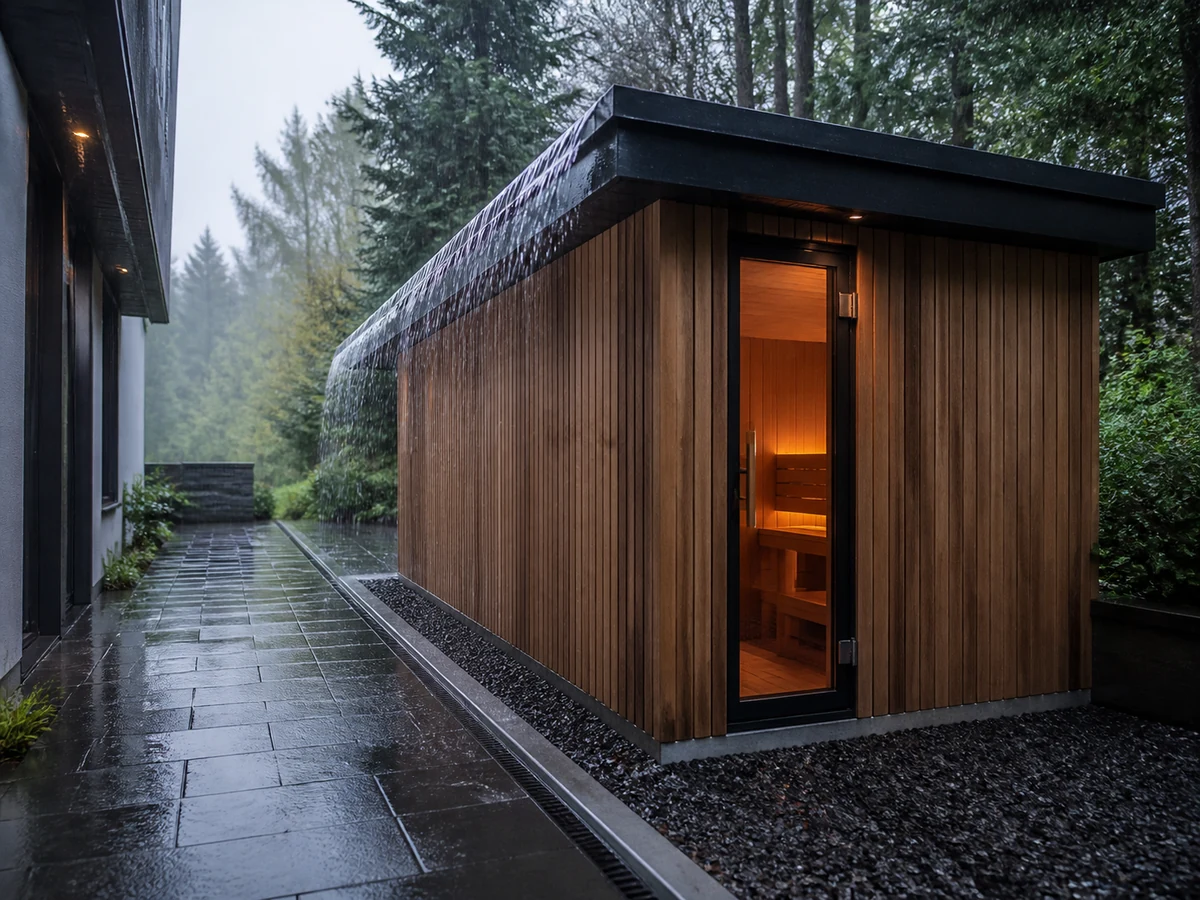
An outdoor sauna is weather-ready only when water is shed, redirected, drained and allowed to dry across the complete product-and-site assembly. A buyer should verify the roof and edges, wall and module joints, doors and glazing, ventilation and service penetrations, base clearance, foundation drainage, compatible materials, installation instructions, maintenance access and acceptance records. A finish may protect a surface, but it cannot correct an inward-sloping sill, an unflashed penetration or ponding at the base.

Start with the approved climate and exposure brief for the exact site, then trace every water path from source to final discharge. Mark which details are supplied with the sauna and which belong to the project designer, installer or operator. Structural loads, anchorage, electrical work, fire separation, glazing, waterproofing and adopted-code decisions must be confirmed for the selected configuration by the responsible qualified professionals and authorities having jurisdiction. Do not release an order from a product photograph or an unsupported waterproof claim.

ILLUSTRATION RESERVED

Outdoor sauna weatherproofing water-path map

Outdoor sauna diagram tracing direct rain, upstream roof runoff, wind-driven rain, splash, cleaning water, snowmelt and drainage.

Planned file: outdoor-sauna-weatherproofing-water-path-map.webp | 1200 x 900 WebP

Generation brief retained

Caption: A buyer should trace every water source to a controlled discharge before reviewing individual materials.

Annotations: direct rain; upstream runoff; wind-driven rain; splash zone; cleaning water; snowmelt; roof edge; opening; base clearance; final drain

Prompt: Create a realistic B2B engineering illustration in a three-quarter elevated view of one complete freestanding outdoor sauna beside paving and a drain. Trace technically coherent arrows for direct roof rain, runoff from an adjacent higher roof edge, wind-driven rain at the door, lower-wall splash, controlled cleaning water, snowmelt, roof-edge discharge, base clearance and final site drain. Arrows must follow plausible gravity and wind paths; no floating pipes, no wiring, no dimensions, no product brand or certification marks. White and pale grey background, dark green linework, amber risk arrows, generous margins, 4:3 composition, suitable for 1200 x 900 WebP.

A buyer should trace every water source to a controlled discharge before reviewing individual materials.

Freeze the weatherproofing basis before comparing bids

The weatherproofing basis is a short, revision-controlled schedule that every bidder receives. It starts after the climate and microclimate work: project location, orientation, shielding, rain and wind exposure, upstream runoff, snowmelt, splash, cleaning method, shutdown state and maintenance capacity are already recorded. The weatherproofing review then asks how the offered enclosure and the site work manage those exposures.

Separate three scopes. The product enclosure includes the factory-supplied roof, walls, openings, joints and instructions. The site interface includes foundation, surrounding levels, drainage, upstream structures, utility routes and any project-applied weather layers. The operating scope includes inspection, cleaning, drying, seasonal preparation and defect response. If these are combined in one vague sentence, missing work is easily priced by nobody.

Utilisation required, preferred et open fields. A required field is a release gate. A preferred field may change only through an approved deviation. An open field has a named owner and due date. The relationship is:

Release status = PASS only when every required item is approved and every open item has an owner and due date

This is a document-control rule, not a statement that an unresolved safety or code item may remain open at installation.

Weatherproofing basis table

Controlled input What the buyer records Pourquoi c'est important Preuves requises Change trigger
Exposure brief Rain direction, upstream runoff, splash, snowmelt, sun, debris and maintenance access Defines what reaches each interface Approved post-1995 climate/exposure schedule or equivalent project record Location, orientation or shielding changes
Product boundary Factory-supplied roof, walls, openings, joints, trims and kits Prevents site work from being assumed inside the product price Controlled product scope drawing Product/configuration changes
Site boundary Foundation, drainage, adjacent roofs/walls and utility routes Connects the product to the building/site water path Project interface drawing Site design or level changes
Installation scope Factory assembly versus field joints, sealants, flashings and finish Determines workmanship and inspection responsibility Installation method and responsibility matrix Installer or assembly route changes
Operating scope Cleaning water, drying, inspection and seasonal actions Determines whether the system can be maintained Operator maintenance plan Venue duty or staffing changes
Acceptance basis Hold points, observation/test method, limits, records and retest Prevents subjective handover disputes Approved inspection and test plan Test method or design revision changes

Do not let a later quotation replace the controlled schedule with a supplier's default assumption. Differences are listed in a bid-deviation register and resolved before purchase-order release.

Trace every water path from source to discharge

Begin with sources, not components. Direct rain may strike the roof and windward wall. Water may also arrive from a higher roof edge, downpipe, irrigation system, pool splash, cleaning hose, melting snow, wet footwear or condensation. Each source has a path, an interface, a planned exit and a responsible owner. A sauna roof can shed its own direct rain correctly while an upstream balcony discharges water onto its door head.

Use a plan and at least one section. Mark high points, falls, roof edges, openings, penetrations, joints, base perimeter and final drain or ground discharge. Photograph the site in dry conditions and, where safe and practical, during actual rain or routine cleaning. Record blocked-drain and debris risks. Do not infer drain capacity or waterproofing compliance from photographs alone.

A useful source balance is:

W_total = W_direct_rain + W_upstream_runoff + W_splash + W_cleaning + W_condensation + W_snowmelt

The terms identify sources; they are not literal volumes unless each is calculated using an approved method. The purpose is to stop the review from considering only direct rain.

For preliminary runoff screening:

V_runoff = A_contributing x d_rain x C_runoff

where A_contributing is all upstream horizontal catchment area, d_rain is rainfall depth for the stated interval and C_runoff is an approved runoff factor. This does not size a drain. Intensity, duration, blockage allowance, local requirements, surface characteristics and downstream capacity remain with the responsible drainage design.

Water-source and path register

Source Path to inspect Intended control Preuve Stop/escalate condition
Direct rain Roof, windward wall, openings and base Shedding, deflection, drained joints and clearance Approved details plus site orientation Missing detail or inward path
Upstream runoff Existing roof/balcony/downpipe to sauna Diversion and controlled discharge Coordinated site section Discharge lands on product/opening/base
Wind-driven rain Door head/jamb/sill, vents and joints Oriented opening, overlaps, seals and drainage Exposure plan and opening details Offered detail assumes sheltered orientation
Splash/cleaning Lower walls, threshold and service side Clearance, compatible surfaces and controlled cleaning Operator method and base detail High-pressure cleaning not approved
Condensation Interior/exterior layers and cold surfaces Vapour/air control and drying route as designed Selected construction detail Hidden layer or drying route undefined
Snowmelt/ice Roof edge, door route, base and drain Safe shedding, storage and drainage Site winter plan Door/drain obstructed or falling-ice risk

A complete record can be summarised as:

D_record = source + path + interface + owner + evidence + acceptance criterion

If any term is missing, the path is not ready for release.

Check roof geometry, edges and junctions

The roof is the first water-shedding layer, but its performance depends on geometry and connections. Verify the roof form and selected material system against the supplier's controlled drawing. Check direction of fall, edge termination, eaves or drips, end conditions, penetrations, roof-to-wall junctions and how site-applied work continues or terminates the system. The article supplies no universal roof slope, membrane, overlap or flashing dimension.

Look above the sauna. Adjacent roofs, trees, parapets and walls can concentrate runoff, debris or drifting. Confirm that the sauna roof is not being treated as a drain for a larger upstream catchment unless the approved design allows it. In snow regions, structural loads, drifting, sliding and falling-ice zones remain with the qualified local design route. A weatherproofing checklist cannot approve structural capacity.

Maintenance access matters. A concealed valley, blocked edge or inaccessible roof joint may be difficult to inspect. The project should define how leaves, snow and deposits are removed without damaging the roof or creating fall risk. Do not require an operator to climb onto a roof unless the approved access and safety method permits it.

Roof release checklist

Roof item Buyer check Preuves requises Installation hold point Acceptance record
Form and fall Matches approved drawing and directs water to intended edge Product/project roof drawing Before weather layer/trim concealment Level/fall record where specified
Edge/drip Water breaks clear of wall and base path Edge section and component schedule Before final edge closure Dated photos by elevation
Roof-to-wall joint Overlap/flashing sequence is defined Controlled junction detail Inspect each layer before cover Layer-labelled photo set
Penetration Compatible collar/flashing/seal route Approved penetration detail Before and after sealing Material/reference and photos
Upstream discharge Other roofs/downpipes do not overload the sauna interface Coordinated site drainage plan Before final placement Site observation and drawing mark-up
Snow/debris/access Load/design route, safe shedding and maintenance path are assigned Local structural/site and maintenance plan Before purchase/final site approval Approved plan and operator instruction

Check wall panels, corners and module joints

Wall weather control is not proved by cladding appearance. Ask how water at the outer face is shed, how joints resist or drain incidental entry, how the assembly dries and how the lower edge terminates. For panelised or modular products, distinguish factory joints from field joints. The installation kit, substrate preparation, sequence and environmental limits for field sealing must be controlled.

Capillary gaps are small but important. Water can be drawn into tight unplanned contacts at horizontal ledges, trim ends and base joints. An approved detail may use overlaps, drips, clearances, drainage paths or capillary breaks. Do not invent one detail for every construction. Verify the exact offered assembly.

Joint movement also matters. Wood, metal, glass, sealants and composite panels respond differently to moisture and temperature. A rigid site-applied filler can fail where the design expects movement. Ask for joint width/tolerance, compatible materials and installation conditions from the responsible system provider. Substitution requires written review.

Wall and module-joint evidence table

Interface Failure mode Preuves à demander Field check Deviation trigger
Vertical panel joint Wind-driven entry or open gap Joint section and assembly instruction Alignment, overlap and fastener check Gap or component differs from drawing
Horizontal joint/ledge Ponding and capillary entry Drip/clearance/drainage detail Fall and drainage path observation Reverse fall or blocked exit
External corner Discontinuous weather layer Corner sequence and trim schedule Pre-cover continuity photos Trim or seal substitution
Module connection Site seal omitted or installed in wrong conditions Module-joint kit and method statement Surface condition and sequence log Temperature/moisture outside instructions
Lower wall edge Splash and trapped moisture Base termination detail Clearance and discharge check Soil/paving raised after design
Repair/access point Defect cannot be inspected or renewed Access and maintenance instruction Confirm removable/visible zones Landscaping/trim blocks access

Check doors, glazing and ventilation openings

Openings interrupt the weather layer. Review the head, jamb and sill as a complete path. The head diverts water, jambs prevent lateral entry, and the sill or threshold sheds/drains water without creating an unsafe step or obstructing door operation. Door alignment and seal compression depend on frame installation and foundation stability. A high-quality door assembly can still leak or bind if installed out of square.

Glazing review includes the selected assembly, supports, seals, drainage, edge protection and interface with adjacent wall/roof details. Exact glass type, thickness and hardware must come from controlled product documents and applicable project requirements. Do not add values to make a checklist look technical.

Ventilation openings need two checks: indoor-air function and exterior weather exposure. A vent position appropriate for airflow may need an exterior hood, baffle or drainage detail supported by the selected design. Never block or resize a required ventilation opening to stop rain without a reviewed thermal/ventilation and safety decision.

Opening interface checklist

Opening zone Vérifier Preuve Acceptance condition
Door head Water is directed away from head/jamb Approved head detail Continuous detail with no upstream discharge onto opening
Jambs Weather layer connects to frame/trim Jamb section and installation method Alignment and continuity recorded before concealment
Sill/threshold Water exits outward; user route remains safe Sill, drip and drainage detail Correct fall, clear exits and smooth door operation
Door seals/hardware Compression, gaps and adjustment match instructions Door assembly documentation Full operation and agreed visual/functional check
Glazing perimeter Supports, seals and drainage match selected assembly Controlled glazing detail No unapproved material or blocked drainage path
Vent/opening exterior Weather protection preserves required airflow Coordinated vent/weather detail Opening area/route unchanged without approval

Check service penetrations and electrical interfaces

Every cable, conduit, sensor route, light, control, drain or accessory that crosses an exterior layer is a potential water path. The selected-product and project drawings should show which penetrations are factory completed and which are made on site. Site drilling without an approved location can damage weather layers, structure, insulation, vapour/air control or required clearances.

A penetration detail normally has a compatible sleeve, collar, flashing or seal arrangement, a prepared substrate and a route that does not direct water inward. Where a cable route uses a drip loop or downward entry, it must still follow the exact electrical and product instructions. This article does not instruct fixed wiring or select protective devices.

Electrical safety takes priority over a cosmetic seal. If water reaches electrical equipment, an enclosure is damaged or the permitted route is uncertain, stop work, isolate as required by the safe project procedure and escalate to qualified personnel. Do not add sealant around energized or unapproved equipment.

Penetration hold-point table

Penetration Pre-work evidence Field record Condition d'arrêt Responsible review
Power/control route Exact product instruction and electrical design Location before drilling and final photos Route conflicts with structure, clearance or weather layer Qualified electrical/project team
Sensor/accessory Approved location and compatible entry method Drawing reference and installed condition Unlisted location or altered sensor behaviour Supplier plus qualified installer
Drain/water accessory Approved fitting, fall and freeze/shutdown method Pressure/leak check under approved method Trapped water, reverse fall or unknown material Plumbing/product route
Ventilation opening Approved size, position and exterior protection Dimensions and weather detail Air path reduced or weather detail unapproved Ventilation/product designer
Site-added fixing Approved substrate and sealing/flash method Fixing schedule and pre-cover photos Penetrates prohibited zone or unknown layer Project designer/installer

IEC 60335-2-53 addresses particular safety requirements for sauna heating appliances and infrared cabins, while IEC 60364-7-703 addresses electrical installations in rooms and cabins containing sauna heaters. Their scope does not prove a HACHILL or third-party product is certified, and local adoption must be checked.

Check the base, foundation and drainage interface

Many weather problems begin at the bottom rather than the roof. The product base must connect to a foundation that is level or sloped exactly as required, supports the full design loads and keeps water from ponding against vulnerable layers. Surrounding paving, soil, decking and landscaping should not bridge a designed clearance or block a drainage/inspection path.

Trace roof discharge and surface water around all sides. Record finished levels, falls, drains, snow storage, irrigation and splash. A concrete slab is not automatically a drainage solution: its elevation, fall, cracks/joints, perimeter and downstream path still matter. Foundation structural capacity, frost movement and anchorage are separate project decisions.

Capillary contact can keep a lower edge wet even when standing water is not visible. The selected detail may require a gap, plinth, membrane, flashing or durable interface. Use the approved drawing. Do not improvise packing pieces or site coatings that alter anchorage, ventilation or drainage.

Base, foundation and drainage responsibility table

Article Supplier/product input Site/project input Point de contrôle Preuve
Footprint and bearing Exact dimensions, support zones and loads Foundation design and survey Before foundation construction Approved drawings and survey
Level/fall Product tolerance/requirement Built level/fall and drainage route Before placement Measured record
Base clearance Product termination/detail Finished paving/soil/deck levels Before landscaping closeout Perimeter photos/dimensions
Surface drainage Product discharge points Falls, drains and downstream capacity Before final placement Site drainage observation/test
Anchorage Product connection/interface data Site-specific structural design Before drilling/fixing Approved design and installation record
Maintenance access Required panel/edge access Clear site zone and safe route Avant la livraison Access dimensions and operator plan
ILLUSTRATION RESERVED

Outdoor sauna roof-to-base weatherproofing section

Outdoor sauna cutaway showing roof edge, wall joint, door sill, service penetration, drained base, foundation fall and maintenance access.

Planned file: outdoor-sauna-weatherproofing-roof-to-base-section.webp | 1200 x 900 WebP

Generation brief retained

Caption: Weatherproofing depends on connected roof, wall, opening, penetration and base details rather than one exterior coating.

Annotations: roof fall; drip edge; roof-wall junction; panel joint; door sill; vent protection; service penetration; base clearance; paving fall; drain; inspection access

Prompt: Create a precise cutaway engineering illustration of a generic outdoor sauna from roof to foundation. Show a plausible roof fall and drip edge, layered roof-to-wall junction, drained wall/panel joint, outward-draining door sill, protected ventilation opening, flashed service penetration, lower-wall clearance, structural base connection, paving falling away to a drain and clear maintenance access. Use numbered callout points with short English labels but no invented dimensions, slopes, product grades, wiring or certifications. No impossible overlaps or trapped drainage. Light neutral background, charcoal and green technical lines with amber hold points, complete object visible, 4:3, 1200 x 900 WebP.

Weatherproofing depends on connected roof, wall, opening, penetration and base details rather than one exterior coating.

Verify materials, finishes, fasteners and substitutions

Weatherproofing performance depends on the complete material system. For exterior wood or cladding, request exact material identification, conditioning where relevant, factory treatment/finish, site preparation, application limits, renewal method and compatible cleaning products. A species name is not a moisture-management detail or service-life guarantee.

For membranes, flashings, sealants, gaskets and coatings, verify substrate compatibility, joint movement, application temperature/moisture limits, curing/protection and shelf/batch controls where relevant. For fasteners and metalwork, verify the controlled schedule, finish, mixed-metal interfaces, drainage/crevice conditions and maintenance. Do not claim that stainless steel is corrosion proof or that one grade eliminates inspection.

Substitution control must cover the sample-to-production path. An approved appearance sample proves only the attributes stated in its approval. It does not approve a different sealant chemistry, membrane, fastener, joint kit or substrate preparation. The buyer records the product/configuration code, drawing revision, approved sample, material schedule and any approved deviations.

Evidence should be ranked:

  1. Applicable law, adopted code and AHJ decision.
  2. Approved project drawings, calculations and exact product instructions.
  3. Purchase-order specification, approved submittal and controlled sample.
  4. Dated inspection, material, test, commissioning and change records.
  5. General catalogue or marketing text.

Lower-level evidence cannot override a higher-level requirement.

Material evidence register

Material/system Required identification Compatibility evidence Installation record Change-control trigger
Exterior wood/cladding Exact offered material and profile Finish, fastener and care instructions Delivery condition and application log Material/profile/finish change
Roof/weather layer Exact system/components Substrate, overlap and junction compatibility Batch/reference and pre-cover photos Membrane/flashing substitution
Sealant/gasket Product and joint use Substrate/movement/application limits Surface and environmental condition log Product, joint or substrate change
Metal/fastener Controlled schedule and finish Mixed-metal, crevice and cleaning review Receiving/installation check Grade/finish/fastener change
Door/glazing assembly Exact selected system Frame, seal, support and drainage documents Alignment and operation record Glass/hardware/seal change
Site repair material Approved repair system Compatibility and preparation method Defect, repair and cure record Any unlisted repair proposal

Inspect factory documentation and receiving condition

Before shipment, the buyer should receive the approved configuration drawing, roof/wall/opening/base details in scope, material/finish schedule, installation instructions, module-joint kit list, care documents, electrical nameplate/instructions and destination-market documents that are actually required. Missing evidence is not corrected by adding a general catalogue.

At receiving, verify identity, quantity, crate condition, water exposure, visible damage, finish condition, straightness/alignment where observable, glass/hardware protection, joint kits, flashings/trims, manuals and labels. Photograph damage before unpacking progresses. If wet packaging is found, record where and how far moisture reached; do not simply dry the surface and discard the evidence.

Quarantine unexplained substitutions, missing kits or damage that could affect weather performance. The deviation record identifies the affected unit/component, drawing/material requirement, observed condition, interim protection, responsible reviewer, disposition and retest requirement.

Receiving weatherproofing checklist

Vérifier Preuve Accept Hold/deviation
Configuration identity Purchase order, approved drawing and labels Exact match Unknown or mixed configuration
Packaging/water exposure Arrival photos and packing inspection Dry/protected as agreed Wet, torn or unrecorded exposure
Roof/wall components Packing list and visible condition Complete and undamaged Bent, cracked, missing or substituted part
Joint/flashing kits Controlled kit list Correct products/quantities Missing label, expired/damaged or alternate product
Door/glazing/hardware Protection and visible inspection No unexplained damage/misalignment Chips, bent hardware, seal or frame concern
Finish/material Approved sample/schedule Controlled match within stated criteria Unapproved variation or damage
Instructions/documents Revision register Current and complete Missing or conflicting instruction

Use installation hold points before details are concealed

A hold point stops work until a named reviewer checks and records the interface. It is most valuable where later work hides a weather layer or makes correction expensive. The inspection plan should identify the drawing, location, check, acceptance criterion, evidence format and release signature. Generic photos are not enough; label the elevation/joint and revision.

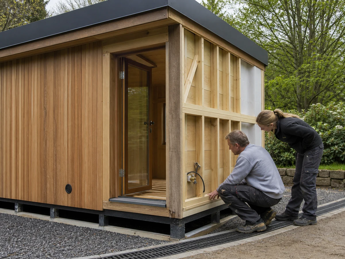
Typical hold points include foundation level and drainage before placement; roof membrane and junctions before trim; module joints before internal/external closure; door/glazing perimeter before cover; service penetrations before and after sealing; and base clearance before landscaping. The exact list follows the selected assembly.

Responsibility matrix

Task Supplier/manufacturer Buyer/specifier Local professionals/AHJ Installer/trades Exploitant
Product weather-envelope details R A/review C C I
Climate/exposure brief C R/A C/approve where required C C
Foundation/site drainage Provide interface data A R/C R I
Structural/anchorage design Provide connection/load data C R/A R to approved design I
Field joints/penetrations Provide approved method A/C C R I
Receiving and hold-point records C A I/C R C
Acceptance observation/test C A C where required R/C R/C
Maintenance and defect response Provide care/limits C I C R/A

R means responsible; A means accountable; C means consulted; I means informed. Project contracts and local requirements control actual duties. This matrix does not transfer legal responsibility.

If the installer proposes a different sealant, flashing, joint sequence or penetration, stop that interface and run change control. Approval records the technical basis, affected drawings, sample, warranty/contract implications if any, installation conditions and revised acceptance method. Do not accept a verbal substitution because it looks similar.

ILLUSTRATION RESERVED

Outdoor sauna weatherproofing inspection and retest workflow

Weatherproofing acceptance workflow showing submittal, receiving, pre-cover hold points, controlled observation, deviation, correction, retest and closeout.

Planned file: outdoor-sauna-weatherproofing-inspection-retest-workflow.webp | 1200 x 900 WebP

Generation brief retained

Caption: A failed weather observation should enter a controlled deviation and retest loop, not an improvised sealant repair.

Annotations: approved submittal; receiving; roof hold point; joint hold point; penetration hold point; base check; controlled observation; deviation; root cause; correction; retest; signed closeout

Prompt: Create a horizontal B2B quality workflow diagram for outdoor sauna weatherproofing acceptance. Show twelve connected stages: approved submittal, receiving identity check, roof pre-cover hold point, wall/module-joint hold point, penetration hold point, base and drainage check, controlled water observation, deviation record, source-path-interface root cause, approved correction, retest, signed closeout. A failed check must loop through deviation, cause, correction and retest. Use simple document and inspection icons, legible short English labels, white background, dark green and charcoal with amber hold points. No logos, certification marks, high-pressure hose depiction, unsafe electrical work or decorative gradients. 4:3, 1200 x 900 WebP.

A failed weather observation should enter a controlled deviation and retest loop, not an improvised sealant repair.

Define acceptance tests without creating damage

Acceptance starts with observation and documentation. Confirm drawing revisions, material records, hold-point closure, visible paths, drainage outlets, door operation, ventilation openings and base clearance. Actual rain observations under known direction and intensity can be useful when safely recorded. A project may also specify a controlled water observation or recognised test method, but the exact method, pressure/flow, duration, area, masking, interior observation, safety controls and pass criteria must be approved before testing.

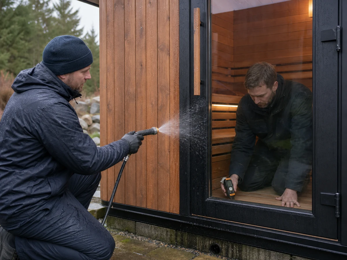
Do not use an uncontrolled high-pressure hose. It can force water into ventilation or joints beyond the intended exposure, damage finishes and produce a result that cannot be compared to any criterion. It can also create electrical risk. A failed observation must be preserved, not immediately covered with unspecified sealant.

Acceptance and dispute record

Stage Preuve Pre-agreed acceptance basis Failure response
Document closeout Approved drawings, schedules, instructions and deviations Current complete set Hold handover until conflicts close
Visual/path review Roof, joints, openings, penetrations, base and drains Approved details and unobstructed paths Record exact location and stop concealment/use if critical
Functional check Door, hardware, vents and drains Exact product/project instructions Adjust/correct by authorised route and recheck
Controlled water observation/test Stated method, conditions, area and interior monitoring Written pass/fail criteria Freeze evidence; investigate source/path/interface
Corrective work Approved repair detail and conditions Repair instruction and reviewer approval Reject improvised repair or unsuitable conditions
Retest/closure Same controlled basis or approved revised method All deviations closed and signed Keep item open; do not claim acceptance

When a disagreement occurs, freeze the evidence: product identity, drawings, materials, site conditions, test setup, water source, timestamps, photos/video, interior observations and operator actions. Trace source, path and interface. Decide whether the cause is product nonconformance, site drainage, installation workmanship, unapproved substitution, test-method error, maintenance condition or an unresolved design input. Approve one correction, retest under the controlled basis and close in writing.

Four composite scenarios that expose weak checklists

Composite scenario 1: the finish was specified but the junction was not

Problème : Water staining appeared below a roof-to-wall junction even though the exterior finish matched the approved colour sample. Cause : The order controlled appearance and coating but did not include a layered roof-to-wall detail or installation hold point. Vérifier : Compare the installed sequence with current drawings, trace upstream runoff and review pre-cover evidence. Correction/prevention: The responsible design/supplier route approves a junction correction and substrate assessment, followed by controlled observation. Future submittals must separate finish evidence from water-shedding and flashing evidence.

Composite scenario 2: module joints were sealed in unsuitable conditions

Problème : Field-applied module seals lost adhesion after early exposure. Cause : The kit was correct, but substrate moisture/cleanliness and application temperature were not recorded; installation continued during unsuitable site conditions. Vérifier : Retain product/batch information, inspect failure pattern and compare the site log with installation limits. Correction/prevention: Remove and repair only through the approved method after substrate assessment. Add environmental-condition recording and a reviewer release to the joint hold point.

Composite scenario 3: the cabin was intact but the base ponded

Problème : Lower cladding and base details remained wet after rain. Cause : Surrounding paving was raised after product approval and fell toward the sauna, blocking the intended clearance and drainage path. Vérifier : Survey finished levels/falls, mark roof and surface runoff, inspect the full perimeter and compare with the approved base detail. Correction/prevention: The site design route restores drainage and clearance without compromising support or anchorage. Add landscaping/paving closeout to the weatherproofing inspection plan.

Composite scenario 4: an uncontrolled test created a false dispute

Problème : Water appeared inside a ventilation opening during a hand-held high-pressure hose test. Cause : No test method, pressure, distance, direction, duration or pass criterion had been agreed; the spray was directed into an intentional air opening. Vérifier : Stop testing, preserve setup evidence, inspect for damage and compare the action with the designed exposure and instructions. Correction/prevention: The responsible team selects an appropriate controlled observation/test or rejects testing if unsuitable, then records the basis. Never convert an arbitrary hose result directly into a product-failure conclusion.

These are composite engineering scenarios, not claims about named HACHILL customers or projects.

Buyer RFQ and submittal checklist

Send the approved exposure basis and require each bidder to identify inclusions, exclusions and deviations. The response should be reviewable without assuming the buyer knows the supplier's internal construction.

RFQ data table

RFQ field Buyer input Supplier response/evidence Release owner
Site/exposure Location, orientation, rain/wind, upstream runoff, splash, snowmelt and cleaning Applicability, assumptions and excluded exposures Buyer/project designer
Product boundary Required format/dimensions and interface locations Controlled scope drawing Buyer/supplier
Roof Site/upstream interfaces and maintenance needs Roof, edge, junction and penetration details Supplier plus project designer
Walls/joints Module/field assembly route Joint sections, kit and method Supplier/installer
Openings/vents Door, glazing and airflow requirements Head/jamb/sill/vent weather details Supplier/project designer
Base/foundation Levels, loads, drainage and access Product base/support/interface data Project structural/civil route
Materials/finish Exposure and evidence requirements Controlled schedule, compatibility and care documents Buyer/supplier
Installation Factory/site scope and site conditions Method, hold points and responsibility Installer/buyer
Réception Observation/test purpose and project risk Supported methods/limitations and criteria Buyer/qualified project route
Maintenance Staffing, access, cleaning and seasonal plan Inspection/care limits Operator/supplier
Documents/compliance Destination market and project requirements Exact available evidence and open items Buyer/supplier/local route
Commercial Quantity, variants, branding/packaging and programme Quotation with deviations and revision Buyer/supplier

HACHILL can review a completed weatherproofing brief against controlled product information, identify which interfaces remain with the site team and prepare model-level submittal questions. That review does not replace local structural, electrical, fire, glazing, wet-area, accessibility, drainage or permitting decisions.

Questions fréquemment posées

Is an outdoor sauna waterproof?
Do not treat waterproof as a universal product-category claim. An outdoor sauna needs a documented weather-management system for its actual exposure: roof and edges, wall/joints, openings, penetrations, base drainage, materials, installation and maintenance. Confirm the selected configuration, test basis and site interfaces rather than relying on one word.
Is exterior coating enough to weatherproof a sauna?
No. A compatible finish may protect an exposed surface, but it cannot correct poor roof runoff, reverse falls, missing flashings, unsealed penetrations, blocked drainage or ponding at the base. Review the complete water path and the exact finish preparation and maintenance instructions.
What should I check at outdoor sauna module joints?
Verify the controlled joint section, supplied kit, overlap/drainage route, movement allowance, substrate preparation, application temperature/moisture limits, sequence and inspection hold point. Record batch/product and site conditions. Any substitute sealant or changed joint needs written review.
How should the base of an outdoor sauna be protected from water?
Use the selected product and project detail. Check foundation level/fall, support and anchorage, perimeter clearance, surrounding paving/soil/deck levels, roof and surface runoff, drains and maintenance access. A slab by itself does not prove that water will leave the base.
Should buyers hose-test an outdoor sauna before acceptance?
Only under an approved, safe and relevant method with stated flow/pressure, direction, distance, duration, observation area and pass criteria. An uncontrolled high-pressure hose can create damage or a false failure, especially at ventilation openings. Electrical safety and product instructions control the decision.
What records prove weatherproofing work was accepted?
Keep the approved exposure brief, product/project drawings, material and kit schedules, receiving record, labelled pre-cover photos, installation-condition logs, deviations, controlled test/observation data, corrections, retest closure and maintenance instructions. Records should identify revision, date, location and responsible reviewer.

Safety, compliance and limitation note

This guide is a buyer verification framework, not a product certification, structural calculation, waterproofing design, glazing design, electrical instruction or universal field-test method. Follow the exact selected product documents and locally applicable building, structural, electrical, fire, accessibility, wet-area and public-venue requirements. Fixed wiring, protective devices, structural loads/anchorage, glazing, site drainage and permit decisions require the appropriate qualified professionals and authorities having jurisdiction. Stop and escalate if approved details are missing, concealed work cannot be verified, site conditions differ, water reaches electrical equipment or a protective/structural component is damaged.

Official reference scope

  • WBDG Moisture Management Strategies explains broader building moisture-control principles. It does not approve a particular sauna detail.
  • IEC 60335-2-53 addresses particular safety requirements for sauna heating appliances and infrared cabins. Citation does not prove product certification.
  • IEC 60364-7-703 addresses electrical installations in rooms and cabins containing sauna heaters; applicability depends on local adoption and the exact installation.
  • ASCE 7 is one structural load standard used in relevant US contexts. The locally adopted edition and qualified design route determine wind/snow values; this article provides none.

Prepare a weatherproofing submittal for review

Before requesting a product recommendation, send the site exposure brief, annotated water-path plan, roof/wall/opening/penetration/base interfaces, foundation and drainage route, material evidence requirements, installation division, hold points, acceptance method, maintenance capacity, destination market, quantity and programme. HACHILL can use that controlled package to discuss outdoor sauna configurations and product-side documents without turning unresolved site work into an unsupported product promise.

Submit a weatherproofing RFQ

Author and technical review box

Editorial scope: HACHILL technical content team. This article separates product-enclosure evidence from site-design and installation responsibility and avoids unverified model, material, test, certification and project claims.

Review before use: Confirm each detail against the selected product documents, approved project drawings and locally applicable requirements. Structural, drainage, electrical, fire, glazing, wet-area and permit decisions remain with the responsible qualified parties and authorities having jurisdiction.