Guide d'ingénierie des bains froids
Compatibilité technique cuve-refroidisseur pour les acheteurs, ingénieurs produits, installateurs et distributeurs.
Réponse directe : Associez une cuve d'immersion froide à un refroidisseur en validant six interfaces pour le système installé exact : puissance thermique, point de fonctionnement hydraulique, raccordements physiques, logique de commande, conditions électriques et de site, et responsabilité de l'installation et de la réception. Commencez par le volume d'eau réel en fonctionnement, les températures de départ et cible, les fenêtres de refroidissement et de remontée en température requises, la température ambiante à l'entrée du condenseur et la boucle d'eau complète. Vérifiez ensuite la puissance de refroidissement liée aux conditions et un point de fonctionnement de pompe qui maintient chaque composant en série dans sa plage de débit admissible.
Le diamètre des raccords, le volume de la cuve et la puissance du refroidisseur sont des critères de présélection utiles, mais aucun ne prouve à lui seul la compatibilité. Un dossier de validation défendable identifie la cuve, le refroidisseur, la pompe, les composants de filtration/traitement, les commandes et les hypothèses de site exacts, puis consigne ce qui a été vérifié, ce qui reste en suspens et ce qui empêcherait la validation.
Portée de la page : cet article traite de l'appariement de l'interface cuve-refroidisseur. Il n'utilise que la logique thermique et de puissance nécessaire pour tester cette interface. Les calculs complets de puissance de refroidissement du projet relèvent de la Guide d'ingénierie thermique et de dimensionnement du refroidisseur pour bassin d'immersion froide; la comparaison entre puissance et puissance de refroidissement utile relève de Cold Plunge Chiller HP vs Cooling Capacity. Les raccordements, limites de fonctionnement et caractéristiques exacts des modèles doivent provenir des données approuvées pour la configuration commandée.
Sur cette page
- Fermez six interfaces avant de déclarer le bassin et le refroidisseur compatibles
- Définissez la boucle d'eau complète et le volume de fonctionnement réel
- Vérifier la puissance thermique avant d'approuver l'appariement du refroidisseur
- Vérifier la puissance de refroidissement utile dans les mêmes conditions
- Trouvez le point de fonctionnement de la pompe sur toute la boucle
- Coordonner les limites de débit, l'amorçage, l'évacuation de l'air et la vidange antigel
- Faire correspondre les capteurs, les points de consigne, les autorisations de pompe et la logique d'alarme
- Vérifier l'air du condenseur, les conditions météorologiques, les condensats et l'espace de service
- Collecter des données synchronisées avant d'attribuer une cause de performance
- Attribuer la responsabilité de l'interface et évaluer les preuves
- Mettre en service selon une limite écrite, puis retester la cause
- Émettre un calendrier d'interface contrôlé et un enregistrement final Go/No-Go
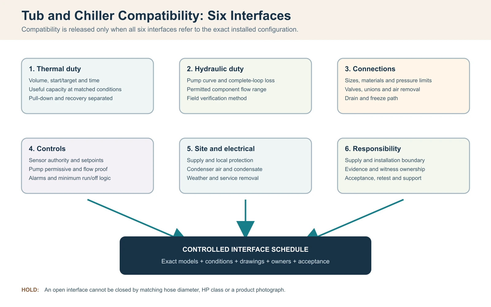
Fermez six interfaces avant de déclarer le bassin et le refroidisseur compatibles
Pour ce processus d'appariement, considérez une cuve d'immersion froide et un refroidisseur comme compatibles uniquement lorsque six interfaces sont validées ensemble : puissance thermique, débit d'eau et perte de charge, raccordements physiques, logique de commande, conditions électriques et de site, et responsabilité de maintenance. Le simple fait d'avoir des diamètres de tuyaux identiques ou d'acheter une classe de puissance supérieure ne prouve pas la compatibilité. La décision de validation doit identifier la cuve, le refroidisseur, la pompe, les composants de filtration et de traitement et la révision de commande exacts, plutôt que deux noms de catégorie.
Commencez par une exigence de fonctionnement en une ligne : volume d'eau réel, températures de départ et cibles, temps de refroidissement autorisé, modèle de session attendu, plage ambiante d'admission du condenseur et emplacement intérieur ou extérieur. Ensuite, dessinez la boucle complète et nommez chaque composant fourni et installé sur site. Une proposition compatible doit montrer que la capacité de refroidissement utile est disponible aux conditions déclarées et que la pompe peut déplacer l'eau à travers la résistance installée complète tout en restant dans la plage de débit autorisée de chaque composant.
Enregistrement de libération de compatibilité du bain et du refroidisseur
| Interface | Question à clore | Preuve de libération |
|---|---|---|
| Thermique | La puissance utile peut-elle répondre aux besoins de tirage et de récupération dans les conditions de conception ? | Données de capacité liées aux conditions et calcul borné |
| Hydraulique | Le point de fonctionnement de la pompe se situe-t-il dans les limites de débit de l'échangeur et du traitement ? | Courbe de pompe, base de perte de charge et méthode de vérification sur site |
| Raccordements | Les dimensions, matériaux, vannes, raccords unions, vidange et chemins d'évacuation d'air sont-ils coordonnés ? | Schéma approuvé du circuit et des raccordements |
| Commandes | Quel dispositif commande la pompe et le compresseur, et qu'est-ce qui arrête un fonctionnement dangereux ? | Séquence de fonctionnement, programme d'alarmes et d'interverrouillages |
| Site/électricité | L'alimentation électrique, l'air du condenseur, les conditions météorologiques, le drainage et l'accès pour la maintenance sont-ils réalisables ? | Plan du site et examen qualifié local si requis |
| Responsabilité | Qui fournit, installe, vérifie et assure le support de chaque interface ? | Matrice approuvée des responsabilités et des acceptations |
Règle de libération : une interface non validée reste un blocage technique, même lorsque les deux produits fonctionnent séparément. N'utilisez pas d'adaptateurs non approuvés, de commandes de dérivation ou de modifications de pompe non approuvées pour forcer une adaptation sur site après livraison.
Définissez la boucle d'eau complète et le volume de fonctionnement réel
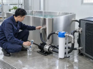
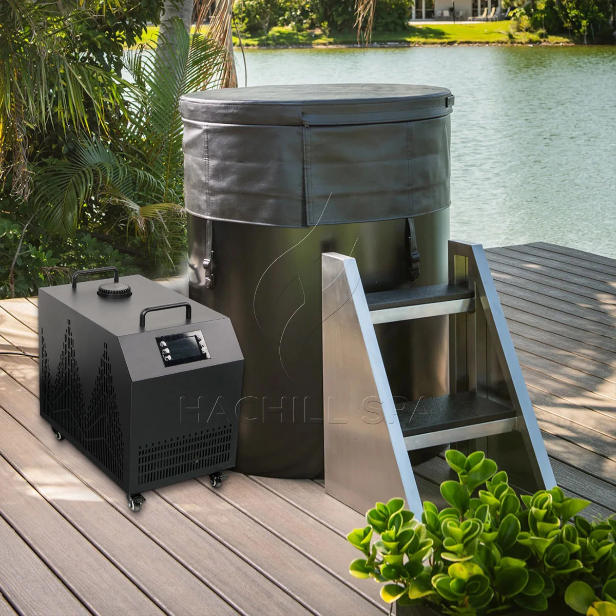
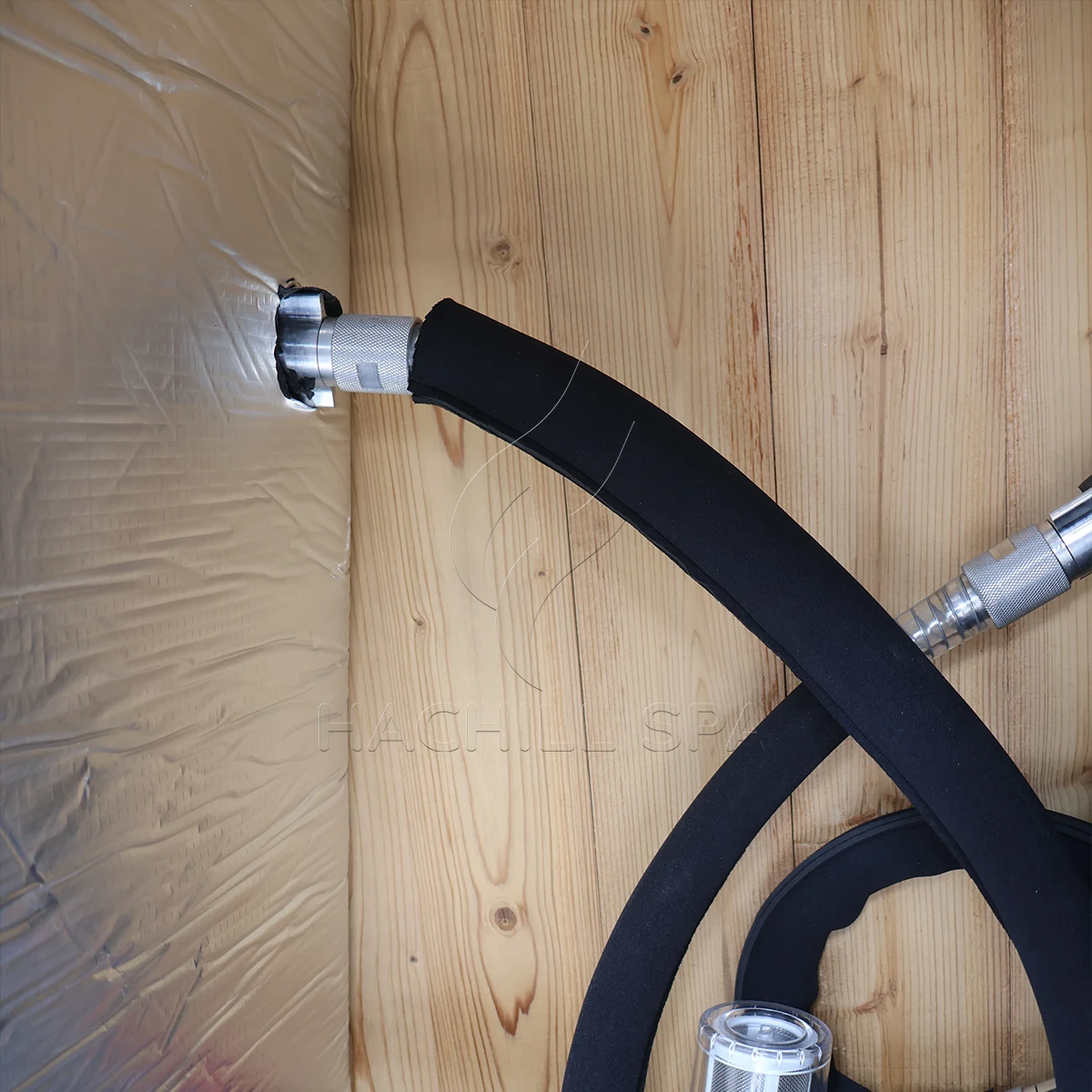
Tracez le chemin de l'eau depuis la sortie du bassin à travers les crépines, la pompe, le filtre, les composants de traitement et l'échangeur de chaleur, puis retour au bassin. Incluez les vannes d'isolement, les clapets anti-retour, les coudes, les réductions, les flexibles, les montées verticales et toute dérivation. L'ordre des composants affecte l'amorçage, l'élimination de l'air, l'accès pour l'entretien et ce qui se passe lorsqu'un filtre se charge. Une photo de deux embouts de flexible ne montre pas le circuit hydraulique installé.
Utilisez le volume d'eau en fonctionnement, et non la capacité géométrique maximale du réservoir. Le volume dépend de la ligne de flottaison approuvée, du déplacement interne, du déplacement des utilisateurs et de savoir si les tuyauteries externes ou un ballon tampon ajoutent un volume d'eau significatif. Mesurez un remplissage avec un compteur adapté lorsque les données du modèle approuvé ne sont pas disponibles, et enregistrez la méthode de mesure. Deviner à partir des dimensions extérieures peut surestimer ou sous-estimer la masse thermique car les sièges, l'épaisseur des parois et le franc-bord ne sont pas de l'eau.
Figez la révision de configuration avec la boucle. Un distributeur peut associer un bassin d'un fournisseur avec un refroidisseur, une pompe et un skid de traitement séparés. Chaque composant peut être individuellement adapté mais incompatible en boucle si les matériaux de raccordement, les pressions nominales, les débits requis ou les hypothèses de contrôle diffèrent. Enregistrez ce qui est dans la caisse, ce que l'installateur fournit et quel dessin contrôle l'agencement final.
Vérifier la puissance thermique avant d'approuver l'appariement du refroidisseur
L'appariement cuve-refroidisseur nécessite toujours un verrou thermique, mais la vérification de compatibilité doit s'arrêter avant de devenir un second processus complet de dimensionnement. Consignez le volume d'eau réel en fonctionnement, les températures initiale et cible, le temps de refroidissement autorisé, l'intervalle de remontée en température prévu, la température ambiante à l'entrée du condenseur, l'état du couvercle et un profil d'utilisation représentatif. L'appariement reste en suspens tant que le refroidisseur sélectionné ne dispose pas de preuves de refroidissement utile applicables à ces conditions.
Pour un écran transparent à eau uniquement, la chaleur sensible peut être estimée avec Q = m x cp x Delta T. Le manuel de thermodynamique du U.S. Department of Energy utilise la même relation de chaleur sensible, et la capacité thermique de l’eau liquide varie avec la température plutôt que d’être une constante immuable. Pour un volume de fonctionnement illustratif de 400 L, approximé à 400 kg d’eau, refroidi de 22 C à 10 C avec cp = 4.186 kJ/kg-K donne environ 5.58 kWh thermique de l'énergie stockée de l'eau. Si une puissance utile nette vérifiée moyenne de 2.4 kW dans les conditions pertinentes, le temps idéal pour l'eau seule serait d'environ 2.33 heures.
Ce calcul est un pont de dépistage entre la charge de la baignoire et les preuves du refroidisseur, et non une promesse de performance HACHILL. Il exclut la chaleur entrant par la cuve, l'eau exposée, la tuyauterie et la pièce ; la chaleur de la pompe ; le gain solaire ; le cycle de régulation ; et les changements de capacité disponible lorsque l'eau et les conditions ambiantes évoluent. N'ajoutez pas de marge en pourcentage générique simplement pour faire paraître le résultat complet. Reportez les gains de chaleur non résolus dans le flux de travail de dimensionnement thermique dédié ou clôturez-les par des tests contrôlés de l'ensemble du système.
Condition de compatibilité thermique
| Champ | Preuves minimales de correspondance | Maintenir le couplage ouvert lorsque |
|---|---|---|
| Volume d'eau en fonctionnement | Ligne d’eau approuvée ou remplissage mesuré, avec volume externe inclus indiqué | On ne connaît que la capacité nominale de la cuve ou les dimensions extérieures |
| Charge de refroidissement initial | Températures de départ/cible et durée autorisée | Le devis ne présente qu’une allégation générique « refroidit à » |
| Régime de récupération | Événement représentatif d’utilisation/remplissage et fenêtre de récupération requise | Un résultat de descente en température nocturne est utilisé comme indicateur indirect d'utilisation intensive |
| État ambiant/couverture | État de la prise d’air du condenseur et état déclaré de couverture/ouverture | Les preuves de capacité ont été produites dans des conditions non correspondantes |
| Preuve de capacité | Résultat utile pour le modèle/la configuration exact(e) dans les conditions applicables | Seuls le HP, la puissance d’entrée ou un maximum non qualifié sont disponibles |
Vérifier la puissance de refroidissement utile dans les mêmes conditions
La puissance en chevaux, la puissance absorbée du compresseur et la puissance frigorifique utile répondent à des questions différentes. Pour la compatibilité, comparez la charge de la baignoire à la capacité de refroidissement indiquée pour la configuration exacte du groupe froid à la température d’eau, à la température ambiante à l’entrée du condenseur, au débit et à l’alimentation électrique pertinents. Un seul point en eau chaude ou en ambiance favorable peut constituer une preuve valable pour ce point tout en restant insuffisant près de la cible du projet.
Maintenez le périmètre d’essai associé à chaque chiffre. Demandez si la capacité indiquée représente le groupe frigorifique seul ou l’ensemble complet fourni, et si le comportement de la pompe, du ventilateur, de l’échangeur thermique et de la régulation est inclus dans le périmètre déclaré. Deux devis peuvent afficher la même valeur de capacité tout en décrivant des conditions différentes ou des parties différentes du système.
Une unité plus grande n’est pas automatiquement une meilleure correspondance. Selon la conception de l’équipement et de la commande, une capacité excessive peut créer un besoin électrique et d’air de condenseur plus important, déplacer l’exigence hydraulique ou produire un cyclage court lorsque la charge active descend sous la plage contrôlable de l’unité. La sélection correcte doit satisfaire le régime valide le plus exigeant tout en restant à l’intérieur de l’enveloppe de fonctionnement permise du modèle exact.
Preuves de capacité nécessaires pour l’adéquation cuve/refroidisseur
| Champ fournisseur | Utilisez-le pour | Ne pas substituer |
|---|---|---|
| Capacité de refroidissement utile | Taux d’évacuation de chaleur aux conditions déclarées d’eau, d’ambiance, de débit et d’alimentation | Entrée pour classe HP ou compresseur |
| Résultat de descente en température | Preuve uniquement lorsque le volume, le départ/la cible, l'ambiance, la couverture et la configuration sont déclarés | Une allégation non étayée sur le nombre d'heures pour atteindre la température |
| Domaine de fonctionnement | Limites autorisées d’eau/d’ambiance/débit pour la révision commandée | Un point d'essai catalogue |
| Puissance électrique absorbée | Analyse de la charge et de l’efficacité du site dans un périmètre défini | Puissance frigorifique |
| Comportement de régulation / charge minimale | Si l’unité sélectionnée peut rester stable lorsque la charge diminue | L'hypothèse selon laquelle une capacité supérieure est toujours plus sûre |
Trouvez le point de fonctionnement de la pompe sur toute la boucle
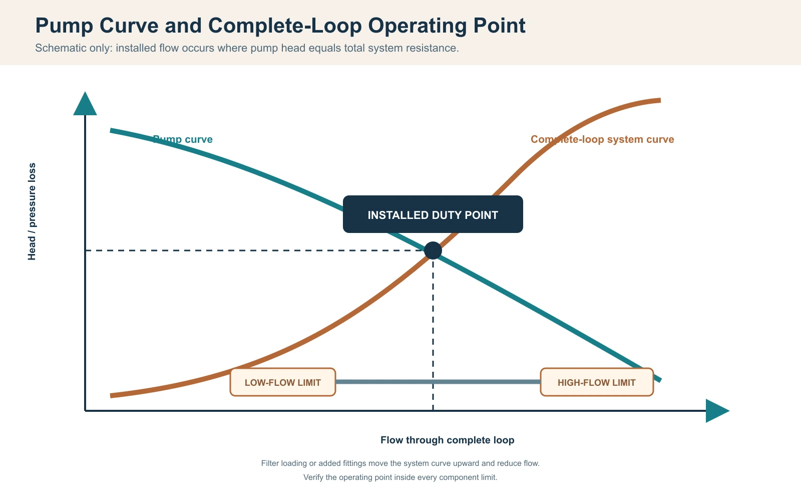
Pour une pompe à vitesse fixe sans dispositif actif de régulation du débit, le point de fonctionnement installé est celui où la courbe de la pompe coupe la courbe de résistance du système ; le Recommandations combinées sur les courbes de pompe et de système du Hydraulic Institute’s documente cette relation. Une commande à vitesse variable ou une vanne de régulation active peut déplacer ou maintenir le point de fonctionnement, mais la capacité de la pompe et la résistance du système complet doivent encore être conciliées. Le débit maximal de la pompe, souvent indiqué à hauteur faible ou nulle, ne peut pas être considéré comme le débit installé. Construisez la résistance à partir du tuyau droit, du flexible, des raccords, des vannes, du filtre ou de la crépine, des dispositifs de traitement et de l'échangeur de chaleur du refroidisseur au débit de conception. Incluez la condition de service : un filtre propre peut passer la mise en service alors qu'un filtre chargé déplace ensuite le système hors de la plage de débit autorisée de l’appareil de refroidissement.
Utilisez les données de perte de charge du fabricant pour les composants lorsqu'elles sont disponibles. Pour la tuyauterie, un concepteur qualifié peut calculer les pertes par frottement et les pertes singulières en utilisant le diamètre, la longueur, le matériau et les raccords approuvés. L'élévation statique dans une boucle de circulation fermée n'est pas traitée de la même manière qu'une hauteur d'aspiration ouverte, mais l'amorçage et l'air emprisonné restent importants. N'ajoutez ni n'omettez pas les termes d'élévation sans définir la configuration réelle.
Un contrôle du bilan thermique côté eau peut appuyer la mise en service : Qpoint = débit massique x cp x Delta T. Pour un débit vérifié illustratif de 30 L/min, le débit massique d'eau est d'environ 0.5 kg/s. Si une différence stable et étalonnée entre l'entrée et la sortie est de 1.0 K, le transfert côté eau est d'environ 0.5 x 4.186 x 1.0 = 2.09 kW. Ce résultat est sensible à la précision du débit, au biais des capteurs, au mélange, à l'alignement temporel et au stockage transitoire ; il n'est pas valable lorsque les relevés sont effectués à des moments ou des endroits différents.
Enregistrement du point de fonctionnement hydraulique
| Article | Preuve de conception | Preuve sur site |
|---|---|---|
| Pompe | Courbe pour le modèle exact, la vitesse et la fréquence | Mode de fonctionnement et indication de service vérifiée |
| Tuyauterie et flexible | Diamètre intérieur, longueur, matériau et cheminement | Révision installée et contrôle des coudes/restrictions |
| Raccords et vannes | Nombre, type et position | Relevé de position des vannes tel qu'installé |
| Filtre/traitement | Perte de charge propre et en service | État et indication de pression lorsqu'elle est fournie |
| Échangeur de chaleur | Plage de débit admissible et perte de charge | Méthode de débit, températures d'entrée/sortie et alarmes |
| Incertitude | Plage d'instrument et précision requise | Identité, statut de vérification, emplacement et horodatage |
Coordonner les limites de débit, l'amorçage, l'évacuation de l'air et la vidange antigel
Un débit trop faible ou excessif peut disqualifier une correspondance. Un faible débit peut réduire le transfert de chaleur côté eau et peut déclencher une protection contre le débit ou le gel ; un débit supérieur à la limite approuvée d’un composant peut dépasser les caractéristiques de l'échangeur de chaleur, du filtre ou des raccords et peut augmenter la perte de charge, le bruit ou l'usure liée à la vitesse selon la conception. Confirmez la plage autorisée pour chaque composant de la série, puis sélectionnez un point de fonctionnement dans la plage applicable la plus étroite avec une marge pour le colmatage normal du filtre.
Placez la pompe et les vannes de manière à ce que le circuit puisse être rempli, purgé et amorcé selon la méthode approuvée. Un problème de démarrage fréquent survient lorsque la pompe contient de l'air : elle semble active mais n'établit pas la circulation, ce qui entraîne un signal de débit faible ou une pompe qui tourne à sec. Vérifiez le niveau d'eau, la position des vannes, les fuites d'aspiration, les points hauts piégés et les étapes d'amorçage du manuel. Ne neutralisez jamais un pressostat de débit pour forcer le fonctionnement du compresseur.
Scénario d'ingénierie : tailles de tuyaux correspondantes, mais alarmes de débit faible répétées
Problème observé : La cuve et le refroidisseur utilisent tous deux la même taille de raccord nominale, mais le système installé se déclenche après l'ajout du filtre.
Cause probable : La sélection a comparé le diamètre du raccord mais a omis la longueur du tuyau, les coudes, la perte de charge du filtre et la courbe de la pompe.
Comment vérifier : Gelez la boucle installée, vérifiez l'état de la vanne et du filtre, calculez la résistance et mesurez le débit selon une méthode approuvée.
Voie de prévention ou corrective : Sélectionnez la pompe en fonction du point de fonctionnement de la boucle complète et conservez une marge de service sans dépasser les limites des composants.
Les installations extérieures ou non chauffées nécessitent une stratégie de protection contre le gel définie. Identifiez chaque point bas, volume piégé et composant nécessitant une vidange ou une circulation protégée. Un raccord de vidange sur la cuve ne vide pas automatiquement le refroidisseur, l'échangeur de chaleur, la pompe ou le tuyau externe. Utilisez les instructions du modèle et une conception professionnelle spécifique au climat ; les dommages dus au gel ne peuvent pas être évités par une procédure générique de blog.
Faire correspondre les capteurs, les points de consigne, les autorisations de pompe et la logique d'alarme
Décidez quel capteur contrôle le système et où il mesure. Un capteur à l'intérieur du refroidisseur peut voir une eau différente de celle du volume principal de la cuve, en particulier à faible débit ou immédiatement après l'entrée d'un utilisateur. Enregistrez l'emplacement du capteur, les hypothèses de mélange, la résolution affichée et toute procédure de décalage. Ne déplacez pas un capteur après acceptation sans réviser la base de test.
La séquence de fonctionnement doit indiquer quand la pompe de circulation démarre, ce qui prouve le débit, quand le compresseur est autorisé, comment la bande morte du point de consigne est appliquée et ce qui se passe après une alarme ou une interruption de courant. Si le contrôleur de la cuve et le refroidisseur externe commandent tous deux la température, des points de consigne contradictoires peuvent créer un cyclage instable. Choisissez une seule autorité de contrôle ou documentez une séquence coordonnée.
L’appariement électrique comprend la tension, la fréquence, la phase, le courant nominal, le comportement au démarrage, les exigences de sectionnement et de protection pour la destination. Le dimensionnement final des conducteurs, la protection contre les surintensités, le sectionnement, la mise à la terre/liaison et toute exigence de GFCI ou de RCD doivent respecter les données de l’équipement commandé, les instructions du fabricant et les règles électriques locales applicables, les travaux réglementés étant réalisés par des professionnels locaux qualifiés. Pour les lieux de travail aux États-Unis, OSHA 1910.333 définit les pratiques de travail liées à la sécurité et réserve les travaux sous tension aux personnes qualifiées. Un adaptateur de fiche ne corrige pas une tension ou une fréquence incompatible.
Scénario d'ingénierie : capacité correcte, température instable
Problème observé : L'eau atteint la cible, mais le compresseur démarre et s'arrête fréquemment et les températures affichées divergent.
Cause probable : Deux contrôleurs utilisent des points de consigne différents, le capteur voit de l'eau de retour mal mélangée, ou la logique de marche/arrêt minimale n'a pas été coordonnée.
Comment vérifier : Consignez les deux affichages, l'état de la pompe, l'état du compresseur, les emplacements des capteurs et les points de consigne de contrôle sur une seule chronologie.
Voie de prévention ou corrective : Approuvez une séquence de fonctionnement unique, l'autorité du capteur et la réponse aux alarmes avant la production ou le câblage sur site.
Vérifier l'air du condenseur, les conditions météorologiques, les condensats et l'espace de service
Un refroidisseur à air rejette la chaleur du bain ainsi que la puissance absorbée du compresseur dans l'air ambiant ; Les recommandations d’ASHRAE sur les condenseurs décrit le rejet de chaleur du condenseur comme la charge de l’évaporateur plus la puissance absorbée du compresseur. L’admission nécessite un air dans la plage ambiante approuvée, et le rejet chaud ne doit pas recirculer vers l’admission. Un appareil placé dans une armoire étroite peut avoir un dégagement visuel suffisant pour les tuyaux, mais une surface libre insuffisante pour le flux d’air, ce qui réduit la puissance ou déclenche la protection haute pression.
Mesurez l'ambiance à l'admission du condenseur lors d'un test de performance, et non à un thermostat de pièce distant. Enregistrez l'exposition solaire, les évacuations à proximité, les murs, les écrans et autres équipements qui peuvent modifier les conditions d'admission. Pour les zones d'installation intérieures, coordonnez la ventilation ou le rejet de chaleur avec l'équipe du bâtiment. Pour une installation extérieure, confirmez l'adéquation de l'enceinte, l'exposition à la pluie et aux débris, le drainage, les effets du vent et toute limite de fonctionnement à basse température selon le manuel exact.
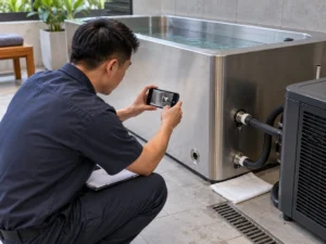
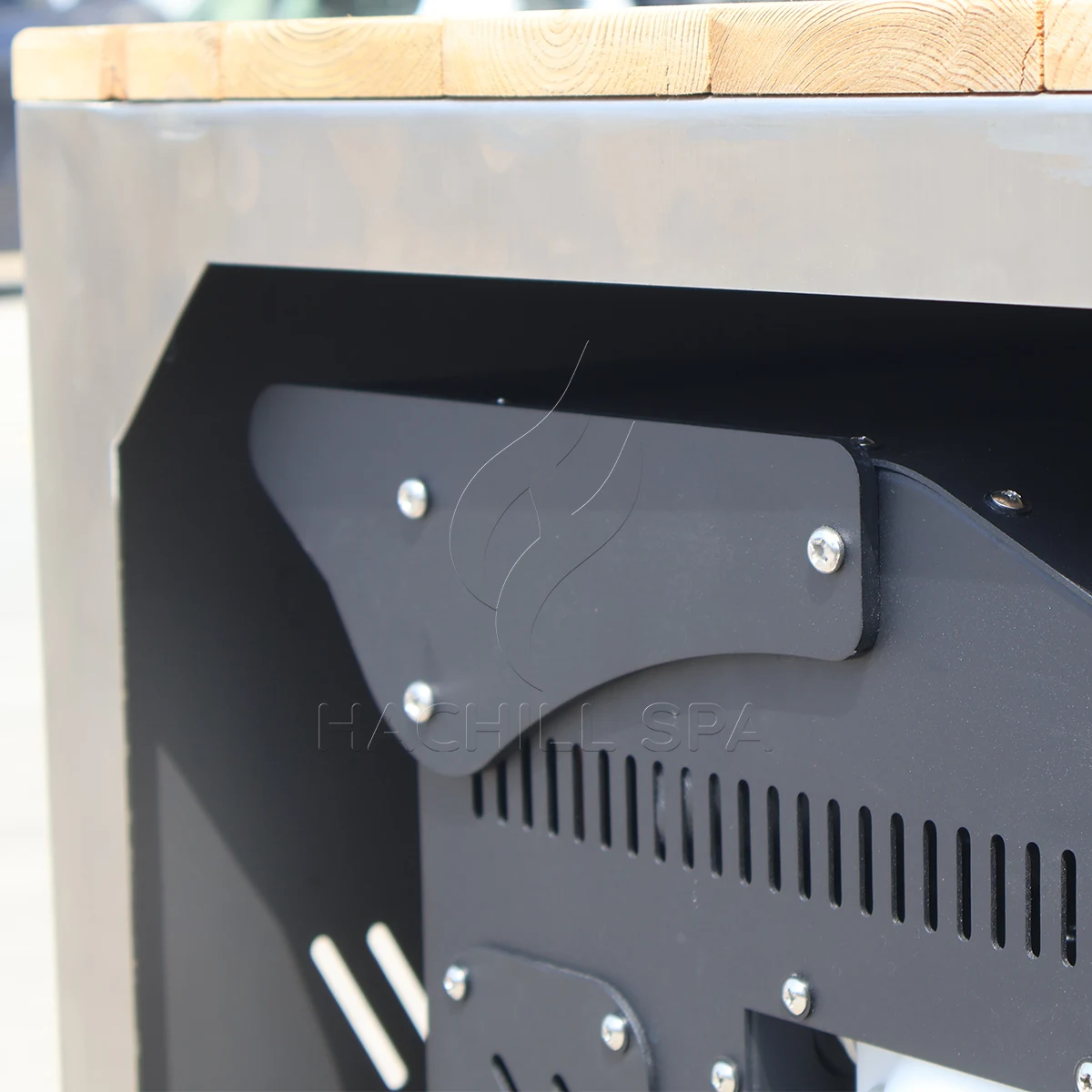
Les tuyaux et composants froids peuvent produire de la condensation. Acheminez-la de manière à ce que l'eau ne puisse pas créer de risque de glissade, endommager les finitions ou atteindre l'équipement électrique. Maintenez l'accès aux filtres, vannes, panneaux et tout composant devant être retiré. Un panneau de service visible sur une image de produit ne prouve pas qu'il peut s'ouvrir après l'intégration de l'unité dans la menuiserie.
Collecter des données synchronisées avant d'attribuer une cause de performance
Collectez un enregistrement synchronisé pour l'ensemble du système. Identifiez la cuve, le refroidisseur, la pompe, le filtre et les révisions de contrôle exacts ; le volume de fonctionnement réel ; l'identité et l'emplacement des capteurs ; la méthode de vérification du débit ; la température ambiante à l'entrée du condenseur ; les températures de l'eau à l'entrée, à la sortie et en vrac mélangé ; l'état de la pompe/du compresseur ; l'état du filtre ; l'état du couvercle ; la limite électrique ; les horodatages et les écarts. Des lectures non synchronisées ne peuvent pas étayer un calcul fiable de la capacité côté eau.
Journal de données de mise en service de la cuve et du refroidisseur
| Point d'enregistrement | Données thermiques/environnementales | Données hydrauliques/de commande | Preuve de configuration |
|---|---|---|---|
| Avant le remplissage | Température de l'eau source et température ambiante de conception | État des vannes, des drains et des filtres | Plans approuvés et identités des composants |
| Démarrer | Températures du mélange en vrac, d'entrée/sortie et d'admission du condenseur | Méthode de débit vérifiée, mode de pompe et point de consigne | Volume d'eau, alimentation et état du couvercle |
| Intervalles fixes | Mêmes capteurs et horodatages | État de la pompe/du compresseur/du ventilateur et alarmes | Ouvertures, solaire ou autres écarts |
| Récupération de session | Avant/après température en vrac mélangé et ambiante | État de contrôle et continuité de la circulation | Nombre d'utilisateurs, timing et perte d'eau |
| Point final | Température en vrac mélangé finale et ambiante à l'admission | Débit stable et transition de contrôle | Références de témoin, d'instrument et d'exception |
Classez un déficit avant d'attribuer la responsabilité. Une cause de sélection thermique peut impliquer des conditions de capacité non appariées ou un gain de chaleur omis. Une cause hydraulique peut impliquer un faible débit, un filtre chargé ou de l'air. Une cause de contrôle peut impliquer la position du capteur, des verrouillages ou des cycles. Une cause de site peut impliquer de l'air de condenseur recirculé, une charge solaire ou une alimentation électrique incorrecte. Une cause de données peut impliquer un débit non vérifié, un biais de capteur ou des horodatages manquants.
Arrêtez le test et faites appel à un service qualifié en cas de répétition de protection électrique ou de pression, de câblage endommagé, d'indication de fuite de réfrigérant ou d'huile, de fumée, de surchauffe, de pompe fonctionnant sans eau, de gel incontrôlé ou de fuite aux interfaces électriques. Les opérateurs peuvent vérifier les conditions visibles autorisées par le manuel ; ils ne doivent pas ouvrir les boîtiers électriques ou de réfrigération ni contourner la protection.
Attribuer la responsabilité de l'interface et évaluer les preuves
Matrice de responsabilité de l'interface cuve et refroidisseur
| Interface | Fournisseur d'équipement | Acheteur/exploitant | Installateur/professionnel local | Preuves de clôture |
|---|---|---|---|---|
| Base de service | Examiner la faisabilité et déclarer les entrées ouvertes | Propre modèle d'utilisation et service cible | Examiner les implications du site | Brief d'exploitation approuvé |
| Sélection thermique | Fournir des preuves de modèle liées aux conditions | Approuver les délais et conditions requis | Vérifier la limite installée | Enregistrement de sélection et base d'acceptation |
| Boucle hydraulique | Fournir les limites et connexions des composants | Approuver la portée fournie/site | Concevoir/installer/vérifier le circuit du site | Schéma de boucle et enregistrement de débit |
| Commandes | Fournir la séquence, les alarmes et les interfaces | Approuver l'autorité d'exploitation | Réaliser l'intégration autorisée sur site | Contrôler le calendrier et l'essai fonctionnel |
| Électrique/site | Fournir les données exactes du modèle et les dégagements | Fournir les données de destination et d'installation | Conception qualifiée et approbation | Registres de libération du site |
| Mise en service | Soutenir les contrôles spécifiques au produit | Fournir un opérateur et un témoin | Vérifier l'installation et les travaux réglementés | Résultat signé, écarts et statut de re-test |
Évaluer les preuves selon leur applicabilité. Un essai témoin spécifique à la commande, réalisé dans des conditions convenues, est le plus probant pour l'acceptation contractuelle. Des preuves indépendantes ou accréditées peuvent étayer la conformité ou la performance uniquement dans le cadre du modèle et de la portée déclarés. Les données fabricant spécifiques au modèle, avec méthode et conditions, soutiennent la sélection technique. Des calculs transparents soutiennent le pré-filtrage. Les brochures génériques, les étiquettes HP et les photographies ne servent qu'à la découverte.
Utiliser des points de blocage avant de commander les pénétrations du site, de libérer la production, d'expédier le système et de l'ouvrir aux utilisateurs. Une référence à une norme ou à une certification décrit une portée ; elle ne prouve pas que le modèle HACHILL, la tension ou la configuration commandés détiennent cette approbation. Maintenir toute preuve de destination requise ouverte jusqu'à ce que le réviseur responsable confirme l'applicabilité exacte.
Mettre en service selon une limite écrite, puis retester la cause
Rédiger l'acceptation avant l'essai sur le terrain. Préciser la configuration, le volume d'eau, les conditions de départ et de cible, le temps autorisé ou le point de capacité côté eau, la plage de température ambiante à l'entrée du condenseur, la plage de débit et la méthode de vérification, l'état du filtre, l'état de la couverture et du solaire, la limite électrique, les emplacements des capteurs, l'état des instruments, le mode de contrôle, le point final et les témoins. Prédéfinir ce qui rend un essai invalide et quel écart peut être accepté.
Acceptation de compatibilité et registre des litiges
| Litige observé | Preuves requises | Disposition |
|---|---|---|
| La descente en température est lente | Volume, températures, ambiance, débit, contrôles et apports de chaleur appariés | Séparer les causes de sélection, hydrauliques, de contrôle, de site et de données |
| Le débit est contesté | Courbe de pompe, résistance installée, état du filtre et méthode de vérification | Corrigez la boucle ou la méthode ; ne déduisez pas le débit de l'apparence |
| Les affichages divergent | Identité du capteur, position, mélange et statut de vérification | Corrigez la base de mesure et refaites le test |
| Le refroidisseur se déclenche | Historique des alarmes, débit d'air, débit, alimentation et limites manuelles | Arrêtez tout travail dangereux ; diagnostic qualifié avant réinitialisation/nouveau test |
| Le périmètre est incomplet | Calendrier d'interface approuvé, dessin et enregistrement d'emballage | Retenir l'installation ou l'acceptation jusqu'à la clôture de la responsabilité |
| Conditions modifiées | Journal des écarts et tolérance pré-agréée | Invalider ou traiter l'essai avant de juger la performance |
Un nouvel essai ne devrait modifier que la cause identifiée et préserver les autres conditions dans la mesure du possible. Si le débit n'était pas vérifié, corriger la méthode et répéter ; si l'air du condenseur était en recirculation, corriger la condition du site et répéter ; si les capteurs étaient biaisés, les vérifier ou les remplacer et répéter. Enregistrer qui autorise le nouvel essai et qui en supporte le coût pour chaque catégorie de cause.
Scénario d'ingénierie : le refroidisseur semble sous-dimensionné uniquement après l'installation
Problème observé : Les données du fournisseur suggéraient une puissance suffisante, mais la descente en température sur site est lente.
Cause probable : L'essai sur site utilise une admission d'air du condenseur plus chaude, un débit plus faible et un bac non couvert, tandis que la base de sélection utilisait des conditions différentes.
Comment vérifier : Concilier chaque entrée d'acceptation et classer les écarts thermiques, hydrauliques, de contrôle, de site et de données.
Voie de prévention ou corrective : Geler les preuves liées aux conditions et la limite de mise en service avant la libération de la commande, puis refaire l'essai uniquement après avoir maîtrisé la cause.
Émettre un calendrier d'interface contrôlé et un enregistrement final Go/No-Go
Le dossier de compatibilité final devrait tenir sur un calendrier contrôlé : modèles et révisions exacts, volume d'eau en service, charges thermiques, preuves et conditions de capacité, point de fonctionnement de la pompe, limites de débit des composants, tailles et matériaux des raccordements, schéma de boucle, séquence de contrôle, alimentation électrique, limite d'air du condenseur, méthode de gel et de vidange, dégagements de service, responsables et essais d'acceptation. Chaque élément ouvert nécessite un responsable, une date d'échéance et un effet sur la libération.
Pour une demande de devis, envoyer le volume d'eau, les températures initiale et cible, les temps de descente et de récupération, les utilisateurs et le calendrier, l'emplacement intérieur/extérieur, la plage de température ambiante, le tracé des canalisations, la portée du filtrage et du traitement, la puissance disponible, l'intégration du contrôle, le marché de destination et les preuves requises. Demander aux fournisseurs de retourner les inclusions, exclusions et hypothèses dans le même calendrier afin que les devis puissent être comparés sans combler les lacunes avec un langage commercial.
- Geler le volume exact du bac et la révision complète de la boucle d'eau.
- Séparer les charges de descente en température, de maintien et de récupération de session.
- Faire correspondre la puissance frigorifique utile aux conditions pertinentes d'eau, d'ambiance, de débit et d'alimentation.
- Tracer ou documenter le point de fonctionnement de la pompe par rapport à la résistance totale de la boucle.
- Confirmer les plages de débit des composants, l'amorçage, l'évacuation de l'air et la vidange antigel.
- Approuver l'autorité des capteurs, les autorisations de pompe, les alarmes et la logique anti-court-cycle.
- Attribuez chaque interface fournie et installée sur site.
- Rédigez les règles d'acceptation, d'écart, d'arrêt, de nouveau test et de litige avant l'expédition.
HACHILL peut examiner un appariement de famille de produits ou de modèle lorsque l'acheteur fournit ces données. Toute valeur de modèle non vérifiée, portée de certification ou hypothèse de site doit rester ouverte jusqu'à ce qu'elle soit étayée par des données spécifiques à la commande ; l'examen ne remplace pas le travail agréé en électricité, structure, santé publique ou réfrigération.
Questions fréquemment posées
Quelle taille de refroidisseur me faut-il pour un bain froid ?
Il n’y a pas de réponse fiable à partir du seul volume de la baignoire. Pour cette page d’appariement, les données nécessaires sont le volume d’exploitation, les températures de départ et cible, les fenêtres de descente en température et de récupération, la température ambiante à l’entrée du condenseur, le programme d’utilisation, l’état de la couverture/isolation et l’hydraulique. Utilisez le guide dédié de dimensionnement thermique pour calculer la charge du projet, puis revenez ici pour finaliser les interfaces baignoire/groupe froid avec des données de modèle liées aux conditions.
La puissance en chevaux du refroidisseur est-elle la même que la capacité de refroidissement ?
N° La puissance en chevaux peut décrire un compresseur ou une classe de taille commerciale, tandis que la capacité de refroidissement utile dépend du système frigorifique complet et des conditions d'essai. Comparez la capacité d'extraction de chaleur aux températures d'eau et ambiante indiquées.
Pourquoi un bain froid peut-il refroidir plus lentement à l’extérieur ?
Un air d’admission de condenseur plus chaud, un apport de chaleur solaire, une recirculation de l’air de refoulement, des tuyauteries exposées et une isolation ou un contrôle de couverture faibles peuvent augmenter la charge du système ou réduire la puissance disponible du refroidisseur. La performance réelle dépend aussi du débit, de l’état du filtre et de l’enveloppe de fonctionnement de l’unité exacte’s.
La pompe de circulation peut-elle être sélectionnée en fonction du débit maximal ?
Non. Le débit maximal ou à hauteur nulle ne montre pas le point de fonctionnement installé. La tuyauterie, les raccords, le filtre et l’échangeur de chaleur créent une perte de charge, tandis que la hauteur statique doit être traitée selon la configuration réelle du circuit ouvert/fermé. Utilisez la courbe exacte de la pompe, la résistance du système complet et la plage de débit approuvée du refroidisseur.
Que doit contenir un rapport de mise en service du refroidisseur ?
Consignez la révision exacte du bain/refroidisseur/pompe, le volume d’eau en service, les températures synchronisées de l’eau et d’entrée au condenseur, la méthode de débit vérifiée, l’état du filtre, l’emplacement des capteurs, les points de consigne de régulation, l’état de la pompe/du compresseur, la limite d’alimentation électrique, les horodatages, les alarmes et tout écart. Comparez l’essai uniquement avec la base d’acceptation convenue au préalable.
Ressources HACHILL associées
Catégorie de produit : bassin d'immersion froide
Utilisez la catégorie de produit pour passer des exigences d'interface système à la gamme de bains froids appropriée.
Les refroidisseurs à immersion froide fonctionnent-ils avec 24/7 ?
Utilisez le guide du cycle de service lorsque la question ouverte est de savoir si le refroidisseur doit fonctionner en continu ou peut cycler autour d'une charge de fonctionnement définie.
Solutions commerciales de bains froids
Utilisez la page de solution commerciale lorsque le type d'acheteur, le lieu et la portée du projet sont désormais plus importants que l'interface cuve-refroidisseur elle-même.
Demander un devis de projet
Utilisez la voie RFQ une fois que le calendrier des interfaces dispose de suffisamment d'entrées finalisées pour une revue fournisseur.
Base de référence
- Département de l'Énergie des États-Unis, DOE-HDBK-1012/1-92 : Thermodynamique, transfert de chaleur et écoulement des fluides – Soutient les relations de chaleur sensible et de transfert de chaleur utilisées pour les calculs de présélection ; il ne s’agit pas d’une norme de performance de bain froid.
- NIST Chemistry WebBook : Eau – Données thermophysiques de référence montrant que la capacité thermique de l’eau liquide dépend de la température ; les calculs de projet doivent déclarer la base des propriétés qu’ils utilisent.
- Hydraulic Institute : courbes combinées de pompe & de système – Base du point de fonctionnement pompe/système ; les courbes de pompe exactes, le mode de régulation et la résistance installée régissent encore le point de service réel.
- ASHRAE Handbook, chapitre 39 : Condenseurs – Base de rejet de chaleur du condenseur de réfrigération ; les manuels exacts de l’équipement régissent les limites ambiantes, les exigences de débit d’air et les dégagements de service.
- OSHA 1910.333 – Référence américaine relative aux pratiques de travail électrique liées à la sécurité au travail, le cas échéant ; elle ne remplace pas les règles de conception électrique du pays de destination ni le manuel de l’équipement.
Limite technique et de sécurité pour Comment assortir une cuve d'immersion froide avec un refroidisseur : Les manuels produit, les plans approuvés, les exigences locales applicables en matière de construction, d’électricité, de santé publique et d’accessibilité, ainsi que les corps de métier qualifiés, ont priorité sur les conseils généraux trouvés sur le Web. Cet article ne revendique ni certification ni performance garantie sur site.
Transformer l’interface en note de cadrage de projet
Envoyez à HACHILL le bain ou la présélection, le volume d’exploitation, le régime de température, la plage ambiante, l’agencement de la boucle, le périmètre de traitement, l’alimentation, la destination et les enregistrements requis. L’équipe peut examiner un appariement tout en laissant ouverts les champs non étayés.