Guia de engenharia para banheira de imersão fria
Compatibilidade técnica entre banheira e resfriador de água para compradores, engenheiros de produto, instaladores e distribuidores.
Resposta direta: Combine uma banheira de imersão fria com um resfriador de água fechando seis interfaces para o sistema exato instalado: carga térmica, ponto de operação hidráulico, conexões físicas, lógica de controle, condições elétricas e de obra e responsabilidade pela instalação e aceitação. Comece pelo volume real de água em operação, temperaturas inicial e alvo, janelas necessárias de resfriamento e recuperação, ambiente de admissão do condensador e o circuito de água completo. Em seguida, verifique a capacidade de resfriamento vinculada às condições e um ponto de operação da bomba que mantenha cada componente da série dentro de sua faixa de vazão permitida.
Tamanho do conector, volume da banheira e potência do resfriador de água são campos úteis de triagem, mas nenhum deles prova compatibilidade por si só. Um registro de liberação defensável identifica a banheira exata, o resfriador de água, a bomba, os componentes de filtragem/tratamento, os controles e as premissas de obra, e então registra o que foi verificado, o que permanece em aberto e o que impediria a liberação.
Escopo da página: este artigo trata da compatibilização da interface entre banheira e resfriador de água. Ele usa apenas lógica térmica e de capacidade suficiente para testar essa interface. Cálculos completos de carga térmica de projeto pertencem a Guia de engenharia térmica e dimensionamento de resfriador para banheira de imersão fria; potência versus capacidade de resfriamento útil pertence a Cold Plunge Chiller HP vs Cooling Capacity. Conexões exatas do modelo, limites de operação e classificações devem vir dos dados aprovados para a configuração pedida.
Nesta página
- Feche seis interfaces antes de chamar a banheira e o resfriador de compatíveis
- Defina o circuito de água completo e o volume real de operação
- Verifique a carga térmica antes de aprovar a compatibilização do resfriador de água
- Verifique a capacidade de resfriamento útil nas mesmas condições
- Encontre o ponto operacional da bomba em todo o circuito
- Limites de fluxo coordenados, purga, remoção de ar e dreno de congelamento
- Corresponder sensores, setpoints, permissivos de bomba e lógica de alarme
- Verificar ar do condensador, clima, condensado e espaço de serviço
- Coletar dados sincronizados antes de atribuir uma causa de desempenho
- Atribuir responsabilidade de interface e classificar as evidências
- Comissionar contra um limite escrito e, em seguida, retestar a causa
- Emitir um cronograma de interface controlado e registro final de aprovação/reprovação
Feche seis interfaces antes de chamar a banheira e o resfriador de compatíveis
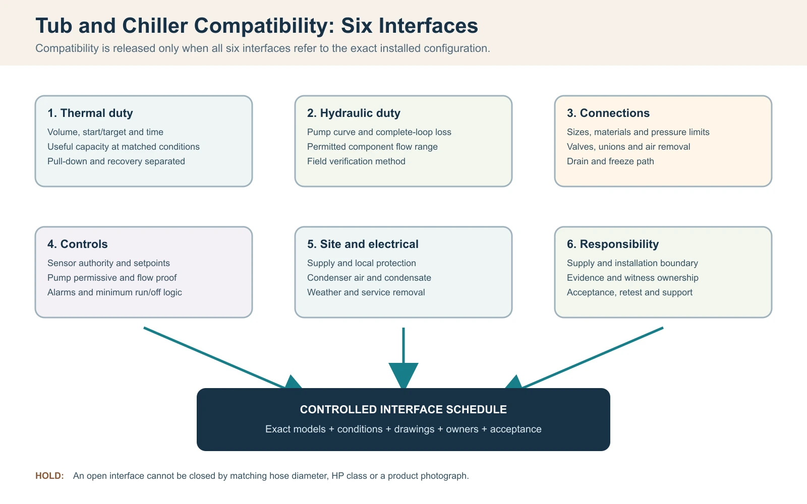
Para este fluxo de compatibilização, considere uma banheira de imersão fria e um resfriador de água compatíveis somente quando seis interfaces fecharem em conjunto: carga térmica, vazão de água e perda de carga, conexões físicas, lógica de controle, condições elétricas e de obra e responsabilidade pelo serviço. Igualar diâmetros de mangueira ou comprar uma classe de potência maior não prova compatibilidade. A decisão de liberação deve identificar a banheira exata, o resfriador de água, a bomba, os componentes de filtragem e tratamento e a revisão de controle, em vez de dois nomes de categoria.
Comece com um requisito operacional de uma linha: volume real de água, temperaturas inicial e alvo, tempo de resfriamento permitido, padrão de sessão esperado, faixa ambiente de entrada do condensador e local interno ou externo. Em seguida, desenhe o loop completo e nomeie cada componente fornecido e instalado no local. Uma proposta compatível deve mostrar que a capacidade de resfriamento útil está disponível nas condições declaradas e que a bomba pode mover água através da resistência instalada completa, permanecendo dentro da faixa de fluxo permitida de cada componente.
Registro de liberação de compatibilidade da banheira e do resfriador
| Interface | Pergunta que deve ser encerrada | Evidência de liberação |
|---|---|---|
| Térmico | A saída útil pode atender às funções de rebaixamento e recuperação na condição de projeto? | Dados de capacidade vinculados à condição e cálculo limitado |
| Hidráulico | O ponto de operação da bomba está dentro dos limites de fluxo do trocador e do tratamento? | Curva da bomba, base de perda de pressão e método de verificação em campo |
| Conexões | Os tamanhos, materiais, válvulas, uniões, dreno e caminhos de remoção de ar estão coordenados? | Desenho aprovado do circuito e das conexões |
| Controles | Qual dispositivo comanda a bomba e o compressor, e o que interrompe a operação insegura? | Sequência de operação, alarmes e programação de intertravamento |
| Local/elétrica | Energia, ar do condensador, clima, drenagem e remoção para manutenção são viáveis? | Planta do local e revisão local qualificada, quando necessário |
| Responsabilidade | Quem fornece, instala, verifica e dá suporte a cada interface? | Matriz de responsabilidade e aceitação aprovada |
Regra de liberação: uma interface em aberto permanece como impedimento de engenharia, mesmo quando ambos os produtos operam separadamente. Não use adaptadores não aprovados, controles de bypass ou alterações de bomba não aprovadas para forçar um ajuste em campo após a entrega.
Defina o circuito de água completo e o volume real de operação
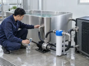
Marque o caminho da água desde a saída da banheira através de filtros, bomba, filtro, componentes de tratamento e trocador de calor, e depois de volta para a banheira. Inclua válvulas de isolamento, válvulas de retenção, cotovelos, redutores, mangueira flexível, elevações verticais e qualquer desvio. A ordem dos componentes afeta a primagem, a remoção de ar, o acesso para manutenção e o que acontece quando um filtro carrega. Uma fotografia de duas pontas de mangueira não mostra o circuito hidráulico instalado.
Use o volume de água operacional, não a capacidade geométrica máxima do vaso. O volume depende da linha d'água aprovada, do deslocamento interno, do deslocamento do usuário e se tubulação externa ou um buffer adiciona volume de água material. Meça um enchimento com um medidor adequado quando os dados do modelo aprovado não estiverem disponíveis e registre o método de medição. Adivinhar a partir de dimensões externas pode superestimar ou subestimar a massa térmica porque assentos, espessura da parede e borda livre não são água.
Congele a revisão da configuração com o loop. Um distribuidor pode combinar uma banheira de um fornecedor com um resfriador, bomba e skid de saneamento separados. Cada componente pode ser individualmente adequado, mas incompatível como um loop se os materiais de conexão, classificações de pressão, fluxos necessários ou suposições de controle diferirem. Registre o que está na caixa, o que o instalador fornece e qual desenho controla o arranjo final.
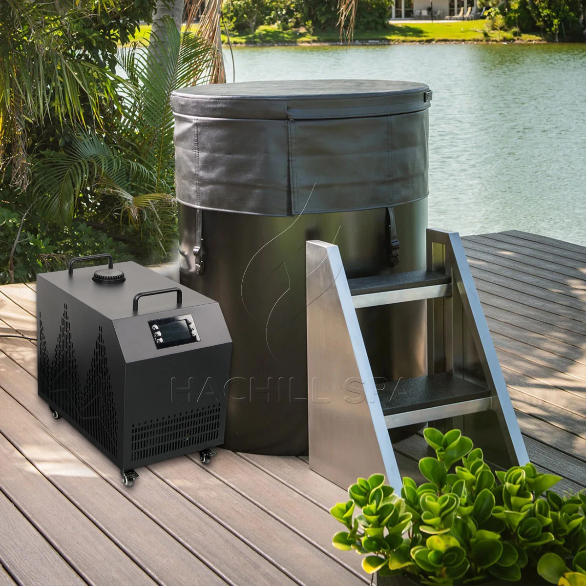
Verifique a carga térmica antes de aprovar a compatibilização do resfriador de água
A compatibilização entre banheira e resfriador de água ainda precisa de um critério térmico, mas a verificação de compatibilidade deve parar antes de se tornar um segundo fluxo completo de dimensionamento. Registre o volume real de água em operação, as temperaturas inicial e alvo, o tempo de resfriamento permitido, o intervalo de recuperação esperado, o ambiente de admissão do condensador, o estado da cobertura e uma programação representativa de uso. O pareamento permanece em aberto até que o resfriador de água selecionado tenha evidência de resfriamento útil aplicável a essas condições.
Para uma triagem transparente apenas com água, o calor sensível pode ser estimado com Q = m x cp x Delta T. O manual de termodinâmica do Departamento de Energia dos EUA usa a mesma relação de calor sensível, e a capacidade térmica da água líquida varia com a temperatura em vez de ser uma constante imutável. Para um volume operacional ilustrativo de 400 L, aproximado como 400 kg de água, resfriando de 22 C para 10 C com cp = 4.186 kJ/kg-K dá aproximadamente 5.58 kWh térmicos de energia armazenada na água. Se uma saída útil líquida verificada tivesse média de 2.4 kW nas condições relevantes, o tempo ideal considerando apenas a água seria de cerca de 2.33 horas.
Este cálculo é uma ponte de triagem entre a carga da banheira e a evidência do chiller, não uma promessa de desempenho da HACHILL. Ele exclui calor que entra pela cuba, água exposta, tubulação e ambiente; calor da bomba; ganho solar; ciclagem de controle; e mudanças na capacidade disponível conforme a água e as condições ambientes variam. Não adicione uma margem percentual genérica apenas para fazer o resultado parecer completo. Leve os ganhos de calor não resolvidos para o fluxo de trabalho dedicado de dimensionamento térmico ou encerre-os com testes controlados de sistema completo.
Critério de compatibilidade térmica
| Campo | Evidência mínima de correspondência | Mantenha o pareamento em aberto quando |
|---|---|---|
| Volume de água em operação | Linha d'água aprovada ou enchimento medido, com volume externo incluído declarado | Apenas a capacidade nominal do vaso ou as dimensões externas são conhecidas |
| Carga térmica de resfriamento inicial | Temperaturas inicial/meta e tempo permitido | O orçamento apresenta apenas uma alegação genérica de “resfria até” |
| Carga térmica de recuperação | Evento representativo de usuário/recarga e janela de recuperação necessária | Um resultado de pull-down durante a noite está sendo usado como proxy de uso intenso |
| Estado do ambiente/cobertura | Condição da entrada do condensador e estado declarado de cobertura/abertura | A evidência de capacidade foi produzida em condições não correspondentes |
| Evidência de capacidade | Resultado útil para o modelo/configuração exato nas condições relevantes | Apenas HP, potência de entrada ou um máximo não qualificado está disponível |
Verifique a capacidade de resfriamento útil nas mesmas condições
Cavalos de força, entrada do compressor e saída de resfriamento útil respondem a perguntas diferentes. Para compatibilidade, compare a carga da banheira com a capacidade de resfriamento declarada para a configuração exata do resfriador na temperatura relevante da água, ambiente de entrada do condensador, vazão e alimentação elétrica. Um único ponto de água morna ou ambiente favorável pode ser evidência válida para esse ponto, embora ainda seja insuficiente perto da meta do projeto.
Mantenha o limite do teste associado a cada número. Pergunte se a capacidade declarada representa apenas a unidade de refrigeração ou o pacote completo fornecido, e se o comportamento da bomba, ventilador, trocador de calor e controle está incluído no limite declarado. Duas cotações podem mostrar o mesmo valor de capacidade enquanto descrevem condições diferentes ou partes diferentes do sistema.
Uma unidade maior não é automaticamente uma combinação melhor. Dependendo do equipamento e do projeto do controle, capacidade excessiva pode criar uma exigência maior de eletricidade e de ar no condensador, deslocar o requisito hidráulico ou produzir ciclagem curta quando a carga ativa cai abaixo da faixa controlável da unidade. A seleção correta deve atender à demanda válida mais exigente enquanto permanece dentro do envelope operacional permitido do modelo exato.
Evidência de capacidade necessária para compatibilizar banheira/resfriador
| Campo do fornecedor | Use para | Não substitua |
|---|---|---|
| Capacidade de resfriamento útil | Taxa de remoção de calor nas condições declaradas de água, ambiente, fluxo e alimentação | Classe de HP ou entrada do compressor |
| Resultado do pull-down | Evidência apenas quando volume, inicial/meta, ambiente, cobertura e configuração forem declarados | Uma alegação não qualificada de horas para atingir a temperatura |
| Envelope operacional | Limites permitidos de água/ambiente/fluxo para a revisão solicitada | Um ponto de teste do catálogo |
| Entrada elétrica | Análise de carga do local e eficiência dentro de um limite definido | Saída de resfriamento |
| Comportamento de controle/carga mínima | Se a unidade selecionada consegue permanecer estável à medida que a carga cai | A suposição de que mais capacidade é sempre mais segura |
Encontre o ponto operacional da bomba em todo o circuito
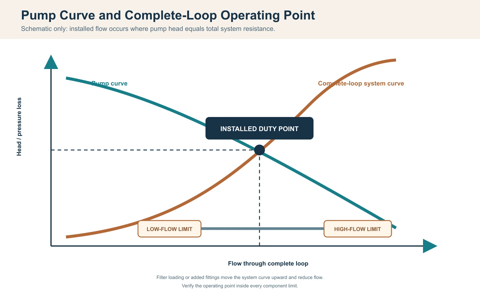
Para uma bomba de velocidade fixa sem um dispositivo ativo de controle de fluxo, o ponto de operação instalado é onde a curva da bomba cruza a curva de resistência do sistema; o Orientação combinada de curva de bomba e sistema do Hydraulic Institute’s documenta essa relação. Controle de velocidade variável ou uma válvula de controle ativa pode deslocar ou manter o ponto de operação, mas a capacidade da bomba e a resistência do sistema completo ainda precisam ser conciliadas. A vazão máxima da bomba, comumente declarada com pouca ou nenhuma altura manométrica, não pode ser tratada como vazão instalada. Construa a resistência a partir de tubo reto, mangueira, conexões, válvulas, filtro ou crivo, dispositivos de tratamento e trocador de calor do chiller na vazão de projeto. Inclua a condição de serviço: um filtro limpo pode passar no comissionamento, enquanto um filtro carregado depois move o sistema para fora da faixa de vazão permitida do chiller’s.
Use os dados de perda de pressão do fabricante para os componentes quando disponíveis. Para tubulações, um projetista qualificado pode calcular as perdas por atrito e perdas menores usando o diâmetro, comprimento, material e conexões aprovados. A elevação estática em um circuito fechado de circulação não é tratada da mesma forma que uma elevação aberta, mas a purga e o ar retido ainda são importantes. Não adicione nem omita termos de elevação sem definir o arranjo real.
Uma verificação de balanço térmico do lado da água pode apoiar a comissionamento: Qdot = vazão mássica x cp x Delta T. Para uma vazão verificada ilustrativa de 30 L/min, a vazão mássica de água é cerca de 0.5 kg/s. Se uma diferença estável e calibrada entre entrada e saída for 1.0 K, a transferência pelo lado da água é aproximadamente 0.5 x 4.186 x 1.0 = 2.09 kW. Este resultado é sensível à precisão do fluxo, ao viés do sensor, à mistura, ao alinhamento temporal e ao armazenamento transitório; não é válido quando as leituras são feitas em momentos ou locais diferentes.
Registo do ponto de funcionamento hidráulico
| Item | Evidência de projeto | Evidência de campo |
|---|---|---|
| Bomba | Curva para modelo exato, velocidade e frequência | Modo de funcionamento e indicação verificada do ponto de trabalho |
| Tubagem e mangueira | Diâmetro interno, comprimento, material e percurso | Revisão instalada e verificação de dobras/restrições |
| Acessórios e válvulas | Quantidade, tipo e posição | Registo da posição das válvulas conforme instalado |
| Filtro/tratamento | Perda de carga limpa e em serviço | Condição e indicação de pressão quando fornecida |
| Permutador de calor | Gama de caudal permitida e perda de carga | Método de caudal, temperatura de entrada/saída e alarmes |
| Incerteza | Gama do instrumento e precisão exigida | Identidade, estado de verificação, localização e carimbo de data/hora |
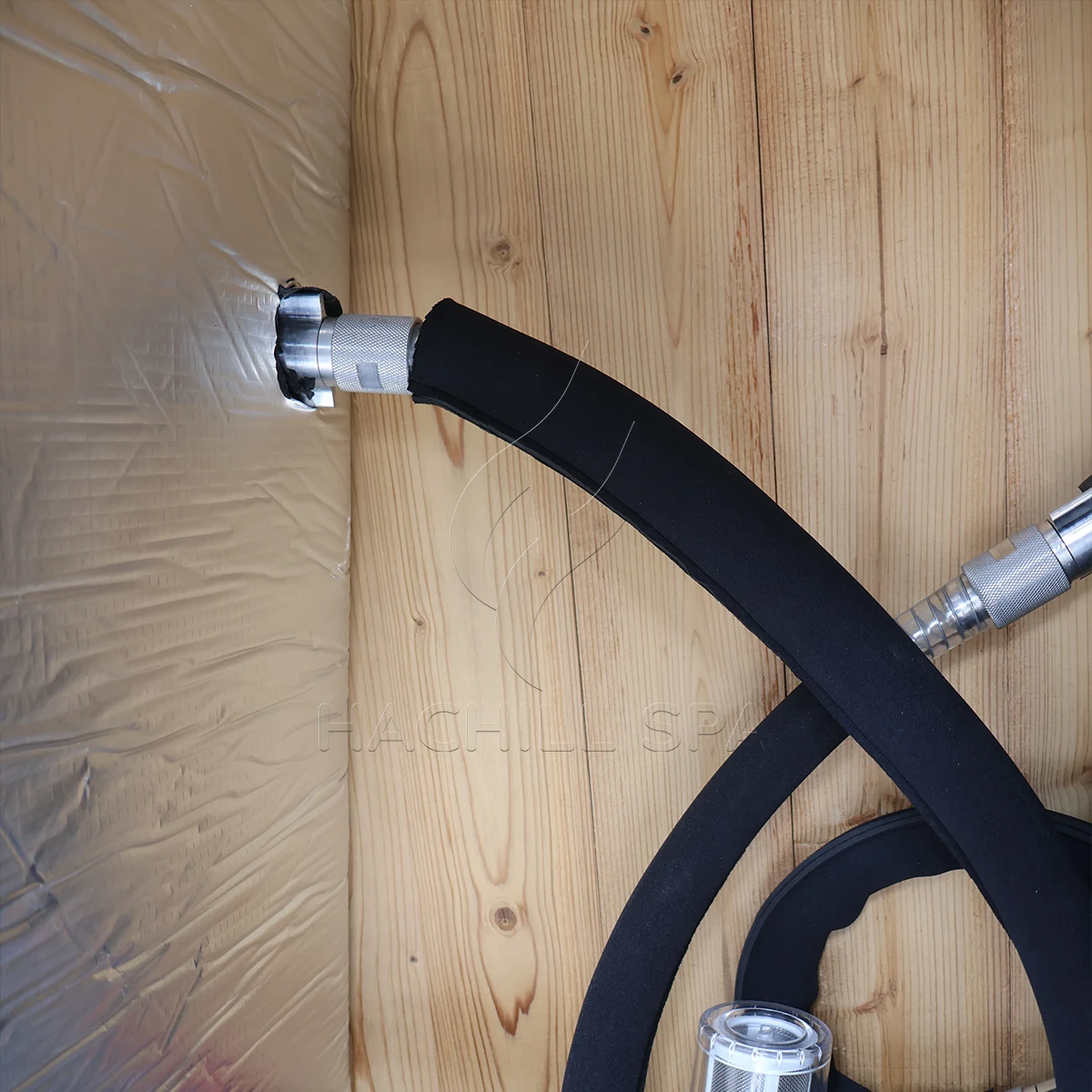
Limites de fluxo coordenados, purga, remoção de ar e dreno de congelamento
Fluxo baixo e fluxo excessivo podem desqualificar uma combinação. Fluxo baixo pode reduzir a transferência de calor do lado da água e pode acionar proteção de fluxo ou de congelamento; fluxo acima do limite aprovado de um componente pode exceder classificações de trocador de calor, filtro ou conexão e pode aumentar queda de pressão, ruído ou desgaste relacionado à velocidade, dependendo do projeto. Confirme a faixa permitida para cada componente da série e então selecione um ponto de operação dentro da faixa aplicável mais estreita, com margem para carregamento normal do filtro.
Posicione a bomba e as válvulas de modo que o circuito possa ser preenchido, purgado e escorvado pelo método aprovado. Um problema frequente de inicialização ocorre quando a bomba contém ar: ela parece ativa, mas não estabelece circulação, fazendo com que o chiller relate fluxo baixo ou a bomba funcione a seco. Verifique o nível da água, a posição das válvulas, vazamentos na sucção, pontos altos retidos e as etapas de escorvamento do manual. Nunca desative um interruptor de fluxo para forçar a operação do compressor.
Cenário de engenharia: Correspondência de tamanhos de mangueira, mas alarmes repetidos de fluxo baixo
Problema observado: A banheira e o chiller usam o mesmo tamanho nominal de conector, mas o sistema instalado desarma após a adição do filtro.
Causa provável: A seleção comparou o diâmetro do conector, mas omitiu o comprimento da mangueira, cotovelos, perda de pressão do filtro e a curva da bomba.
Como verificar: Congele o circuito instalado, verifique a condição das válvulas e do filtro, calcule a resistência e meça o fluxo por um método aprovado.
Caminho de prevenção ou correção: Selecione a bomba a partir do ponto de operação do circuito completo e mantenha uma margem de serviço sem exceder os limites dos componentes.
Instalações externas ou sem aquecimento precisam de uma estratégia definida contra congelamento. Identifique todos os pontos baixos, volumes retidos e componentes que exigem drenagem ou circulação protegida. Um dreno na banheira não esvazia automaticamente o chiller, o trocador de calor, a bomba ou a mangueira externa. Use as instruções do modelo e o projeto profissional específico para o clima; danos por congelamento não podem ser evitados por um procedimento genérico de blog.
Corresponder sensores, setpoints, permissivos de bomba e lógica de alarme
Decida qual sensor controla o sistema e onde ele mede. Um sensor dentro do chiller pode ver água diferente da mistura no tanque, especialmente em baixo fluxo ou imediatamente após um usuário entrar. Registre a localização do sensor, suposições de mistura, resolução exibida e qualquer procedimento de offset. Não mova um sensor após a aceitação sem revisar a base do teste.
A sequência de operação deve indicar quando a bomba de circulação inicia, o que comprova o fluxo, quando o compressor é permitido, como o deadband do setpoint é aplicado e o que acontece após um alarme ou interrupção de energia. Se o controlador do tanque e o chiller externo comandarem a temperatura, setpoints conflitantes podem causar ciclos instáveis. Escolha uma autoridade de controle ou documente uma sequência coordenada.
A compatibilidade elétrica inclui tensão, frequência, fase, corrente nominal, comportamento de partida, requisitos de seccionamento e proteção para o destino. O dimensionamento final dos condutores, a proteção contra sobrecorrente, o seccionamento, o aterramento/equipotencialização e qualquer requisito de GFCI ou RCD devem seguir os dados do equipamento encomendado, as instruções do fabricante e as regras elétricas locais aplicáveis, com trabalho regulamentado concluído por profissionais locais qualificados. Para locais de trabalho nos EUA, OSHA 1910.333 define práticas de trabalho relacionadas à segurança e restringe trabalhos energizados a pessoas qualificadas. Um adaptador de plugue não corrige tensão ou frequência incompatíveis.
Cenário de engenharia: capacidade correta, temperatura instável
Problema observado: A água atinge o alvo, mas o compressor liga e desliga com frequência e as temperaturas exibidas discordam.
Causa provável: Dois controladores usam setpoints diferentes, o sensor vê água de retorno mal misturada ou a lógica mínima de funcionamento/desligamento não foi coordenada.
Como verificar: Registre ambas as exibições, estado da bomba, estado do compressor, localizações dos sensores e setpoints de controle em uma única linha do tempo.
Caminho de prevenção ou correção: Aprove uma única sequência de operação, autoridade do sensor e resposta a alarmes antes da produção ou fiação no local.
Verificar ar do condensador, clima, condensado e espaço de serviço
Um chiller resfriado a ar rejeita o calor da banheira mais a potência do compressor para o ar ao redor; Orientação sobre condensadores da ASHRAE’s descreve a rejeição de calor do condensador como a carga do evaporador mais a energia de entrada do compressor. A admissão precisa de ar dentro da faixa ambiente aprovada, e a descarga quente não deve recircular para a admissão. Uma unidade colocada dentro de um gabinete apertado pode ter folga visual suficiente para mangueiras, mas área livre insuficiente para fluxo de ar, causando redução de rendimento ou proteção de alta pressão.
Meça o ambiente na entrada do condensador durante um teste de desempenho, não em um termostato distante da sala. Registre exposição solar, exaustões próximas, paredes, telas e outros equipamentos que podem alterar as condições de entrada. Para áreas de planta internas, coordene ventilação ou rejeição de calor com a equipe do edifício. Para colocação externa, confirme a adequação do invólucro, exposição a chuva e detritos, drenagem, efeitos do vento e qualquer limite operacional de baixa temperatura do manual exato.
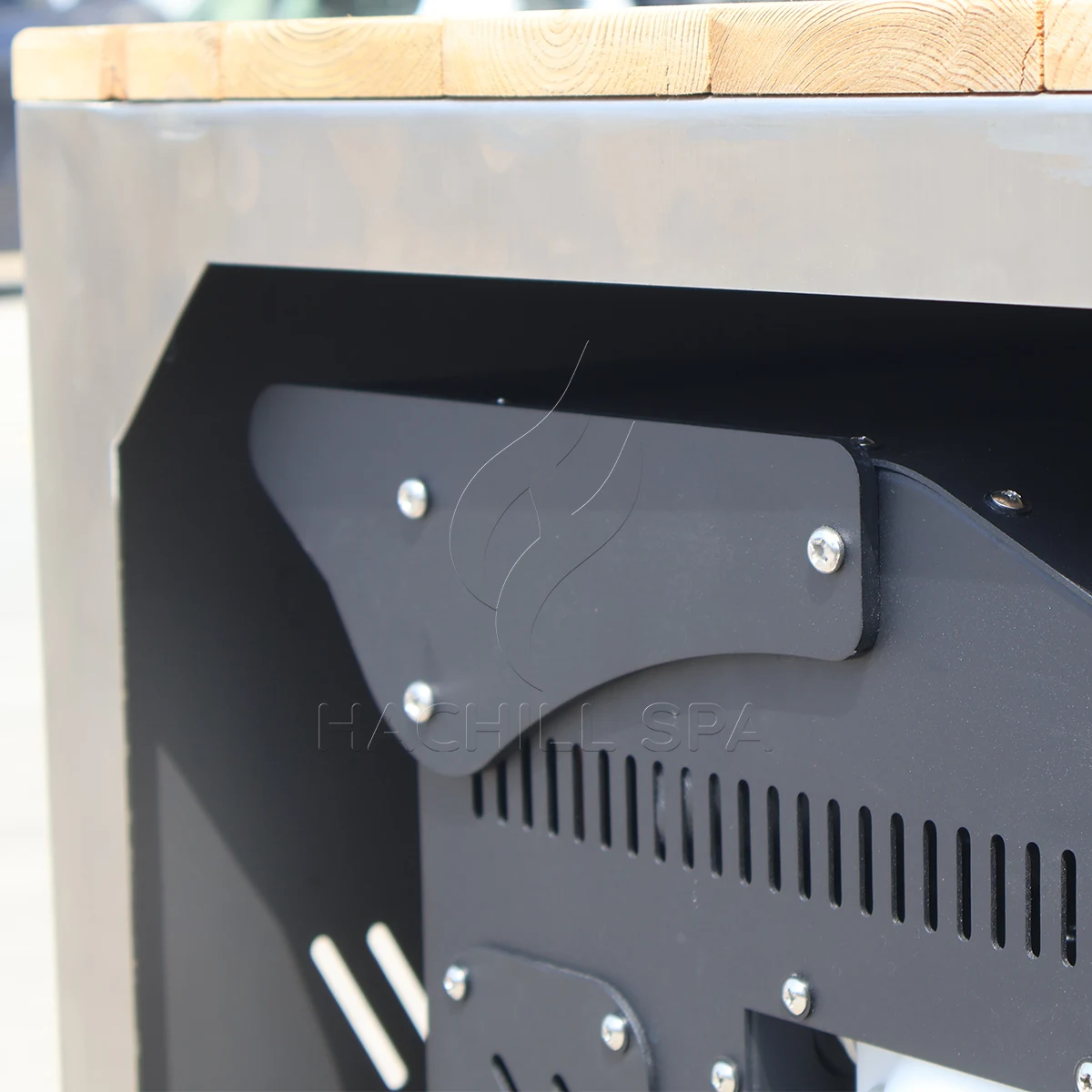
Tubos e componentes frios podem produzir condensação. Direcione-a para que a água não possa criar exposição a escorregões, danificar acabamentos ou atingir equipamentos elétricos. Mantenha acesso a filtros, válvulas, painéis e qualquer componente que deva ser removido. Um painel de serviço visível em uma imagem do produto não prova que ele pode abrir depois que a unidade é embutida em marcenaria.
Coletar dados sincronizados antes de atribuir uma causa de desempenho
Colete um registro sincronizado para o sistema completo. Identifique o tanque exato, chiller, bomba, filtro e revisões de controle; volume operacional real; identidade e localização do sensor; método de verificação de fluxo; ambiente na entrada do condensador; temperaturas de entrada, saída e mistura do tanque; estado da bomba/compressor; condição do filtro; estado da tampa; limite elétrico; carimbos de tempo e desvios. Leituras não sincronizadas não podem suportar um cálculo confiável de capacidade no lado da água.
Registro de dados de comissionamento do tanque e chiller
| Ponto de registro | Dados térmicos/ambientais | Dados hidráulicos/controle | Evidência de configuração |
|---|---|---|---|
| Antes do enchimento | Temperatura da água de origem e ambiente de projeto | Estado da válvula, dreno e filtro | Desenhos aprovados e identidades dos componentes |
| Iniciar | Temperaturas do volume misto, entrada/saída e entrada do condensador | Método de fluxo verificado, modo da bomba e setpoint | Volume de água, abastecimento e estado da cobertura |
| Intervalos fixos | Mesmos sensores e carimbos de tempo | Estado da bomba/compressor/ventilador e alarmes | Aberturas, solar ou outros desvios |
| Recuperação da sessão | Volume misto e ambiente antes/depois | Estado de controle e continuidade da circulação | Número de usuários, tempo e perda de água |
| Ponto final | Volume misto final e ambiente de entrada | Fluxo estável e transição de controle | Referências de testemunha, instrumento e exceção |
Classifique uma deficiência antes de atribuir responsabilidade. Uma causa de seleção térmica pode envolver condições de capacidade incompatíveis ou ganho de calor omitido. Uma causa hidráulica pode envolver baixo fluxo, filtro carregado ou ar. Uma causa de controle pode envolver posição do sensor, intertravamentos ou ciclagem. Uma causa de local pode envolver ar do condensador recirculado, carga solar ou fornecimento elétrico incorreto. Uma causa de dados pode envolver fluxo não verificado, viés do sensor ou carimbos de tempo ausentes.
Pare o teste e use serviço qualificado para proteção elétrica ou de pressão repetida, fiação danificada, indicação de vazamento de refrigerante ou óleo, fumaça, superaquecimento, bomba funcionando sem água, congelamento descontrolado ou vazamento em interfaces elétricas. Os operadores podem verificar condições visíveis permitidas pelo manual; eles não devem abrir invólucros elétricos ou de refrigeração ou contornar a proteção.
Atribuir responsabilidade de interface e classificar as evidências
Matriz de responsabilidades da interface entre banheira e chiller
| Interface | Fornecedor de equipamentos | Comprador/operador | Instalador/profissional local | Evidência de conclusão |
|---|---|---|---|---|
| Base de serviço | Revisar viabilidade e declarar entradas em aberto | Padrão de uso próprio e serviço-alvo | Revisar implicações do local | Brief operacional aprovado |
| Seleção térmica | Fornecer evidência de modelo condicionado | Aprovar tempos e condições exigidos | Verificar limite instalado | Registro de seleção e base de aceitação |
| Circuito hidráulico | Fornecer limites e conexões dos componentes | Aprovar escopo fornecido/no local | Projetar/instalar/verificar circuito no local | Desenho do circuito e registro de fluxo |
| Controles | Fornecer sequência, alarmes e interfaces | Aprovar autoridade operacional | Concluir integração permitida no local | Cronograma de controle e teste funcional |
| Elétrico/local | Fornecer dados exatos do modelo e folgas | Fornecer destino e entradas das instalações | Projeto qualificado e aprovação | Registros de liberação do local |
| Comissionamento | Suportar verificações específicas do produto | Fornecer operador e testemunha | Verificar instalação e trabalho regulamentado | Resultado assinado, desvios e status de reteste |
Classifique as evidências por aplicabilidade. Um teste testemunhado específico do pedido, em condições acordadas, é o mais forte para aceitação contratual. Evidências independentes ou acreditadas podem apoiar conformidade ou desempenho apenas dentro do modelo e escopo declarados. Dados do fabricante específicos do modelo, com método e condições, apoiam a seleção de engenharia. Cálculos transparentes apoiam a triagem. Brochuras genéricas, etiquetas de HP e fotografias apoiam apenas a descoberta.
Use pontos de retenção antes de solicitar penetrações no local, liberar a produção, despachar o sistema e abri-lo aos usuários. Uma referência de norma ou certificação descreve um escopo; ela não prova que o modelo, a tensão ou a configuração HACHILL pedidos possuem essa aprovação. Mantenha qualquer evidência de destino necessária em aberto até que o revisor responsável confirme a aplicabilidade exata.
Comissionar contra um limite escrito e, em seguida, retestar a causa
Redija a aceitação antes do teste de campo. Declare configuração, volume de água, condições iniciais e alvo, tempo permitido ou ponto de capacidade do lado da água, faixa de temperatura ambiente na entrada do condensador, faixa de vazão e método de verificação, condição do filtro, cobertura e estado solar, limite elétrico, locais dos sensores, status dos instrumentos, modo de controle, ponto final e testemunhas. Predefina o que torna uma execução inválida e qual desvio pode ser aceito.
Registro de aceitação de compatibilidade e disputas
| Disputa observada | Evidências necessárias | Disposição |
|---|---|---|
| O resfriamento está lento | Volume, temperaturas, ambiente, vazão, controles e ganhos de calor correspondentes | Causas separadas de seleção, hidráulica, controle, local e dados |
| A vazão é disputada | Curva da bomba, resistência instalada, estado do filtro e método de verificação | Corrija o circuito ou o método; não infira vazão pela aparência |
| Os displays discordam | Identidade do sensor, posição, mistura e status de verificação | Corrija a base de medição e repita o teste |
| O chiller desarma | Histórico de alarmes, fluxo de ar, vazão, alimentação e limites manuais | Pare o trabalho inseguro; diagnóstico qualificado antes de rearmar/retestar |
| O escopo está incompleto | Cronograma de interface aprovado, desenho e registro de embalagem | Segure a instalação ou aceitação até que a responsabilidade seja encerrada |
| Condições alteradas | Registro de desvios e tolerância pré-acordada | Invalidar ou dispor do lote antes de julgar o desempenho |
Um novo teste deve alterar apenas a causa identificada e preservar as demais condições tanto quanto prático. Se o fluxo não foi verificado, corrija o método e repita; se o ar do condensador estava recirculando, corrija a condição do local e repita; se os sensores estavam enviesados, verifique ou substitua-os e repita. Registre quem autoriza o novo teste e quem arca com seu custo em cada categoria de causa.
Cenário de engenharia: O chiller parece subdimensionado somente após a instalação
Problema observado: Os dados do fornecedor sugeriam saída adequada, mas o pull-down em campo está lento.
Causa provável: O teste no local usa entrada do condensador mais quente, fluxo menor e um tanque descoberto, enquanto a base de seleção usou condições diferentes.
Como verificar: Reconcilie cada entrada de aceitação e classifique os desvios térmicos, hidráulicos, de controle, de local e de dados.
Caminho de prevenção ou correção: Congele as evidências vinculadas às condições e o limite de comissionamento antes da liberação do pedido de compra e, em seguida, repita o teste somente após a causa ser controlada.
Emitir um cronograma de interface controlado e registro final de aprovação/reprovação
O registro final de compatibilidade deve constar em um cronograma controlado: modelos e revisões exatos, volume de água operacional, cargas térmicas, evidências e condições de capacidade, ponto de operação da bomba, limites de fluxo dos componentes, tamanhos e materiais das conexões, desenho do circuito, sequência de controle, alimentação elétrica, limite de ar do condensador, método de congelamento e drenagem, folgas de serviço, responsáveis e testes de aceitação. Cada item em aberto precisa de um responsável, data de vencimento e efeito na liberação.
Para um pedido de cotação, envie o volume de água, as temperaturas inicial e alvo, os tempos de resfriamento e recuperação, os usuários e o cronograma, a localização interna/externa, a faixa de temperatura ambiente, o percurso da tubulação, o escopo de filtragem e tratamento, a energia disponível, a integração de controle, o mercado de destino e as evidências necessárias. Peça aos fornecedores que retornem inclusões, exclusões e premissas no mesmo cronograma para que as cotações possam ser comparadas sem preencher lacunas com linguagem de vendas.
- Congele o volume exato da banheira e a revisão completa do circuito de água.
- Separe as funções de resfriamento inicial, manutenção e recuperação entre sessões.
- Corresponda à capacidade de resfriamento útil nas condições relevantes de água, ambiente, fluxo e fornecimento.
- Trace ou documente o ponto de operação da bomba contra a resistência total do circuito.
- Confirme as faixas de fluxo dos componentes, a escorva, a remoção de ar e o dreno para congelamento.
- Aprove a autoridade do sensor, as permissões da bomba, os alarmes e a lógica anti-curto-ciclo.
- Atribua cada interface fornecida e instalada no local.
- Escreva as regras de aceitação, desvio, parada, reteste e disputa antes do envio.
A HACHILL pode revisar um emparelhamento de família de produtos ou modelo quando o comprador fornecer esses dados. Qualquer valor de modelo não verificado, escopo de certificação ou premissa do local deve permanecer em aberto até ser suportado por dados específicos do pedido; a revisão não substitui o trabalho licenciado de engenharia elétrica, estrutural, de saúde pública ou de refrigeração.
Perguntas frequentes
Qual tamanho de resfriador eu preciso para uma banheira de imersão fria?
Não há resposta confiável apenas pelo volume da banheira. Para esta página de correspondência, as entradas necessárias são volume operacional, temperaturas inicial e alvo, janelas de resfriamento e recuperação, ambiente de entrada do condensador, cronograma do usuário, estado de capa/isolamento e hidráulica. Use o guia dedicado de dimensionamento térmico para calcular a carga do projeto, depois retorne aqui para fechar as interfaces banheira/resfriador com dados de modelo vinculados às condições.
A potência do resfriador em cavalos é a mesma que a capacidade de refrigeração?
Nº. A potência em cavalos pode descrever um compressor ou uma classe de tamanho comercial, enquanto a capacidade útil de resfriamento depende do sistema de refrigeração completo e das condições de teste. Compare a capacidade de remoção de calor nas temperaturas de água e ambiente indicadas.
Por que uma banheira de imersão fria pode esfriar mais lentamente ao ar livre?
Ar de entrada do condensador mais quente, ganho de calor solar, recirculação do ar de descarga, tubulações expostas e isolamento ou controle de cobertura fracos podem aumentar a carga do sistema ou reduzir a saída disponível do chiller. O desempenho real também depende da vazão, da condição do filtro e do envelope operacional da unidade exata.
A bomba de circulação pode ser selecionada pelo fluxo máximo?
Não. Vazão máxima ou a zero altura manométrica não mostra o ponto de operação instalado. Tubulação, conexões, filtro e trocador de calor criam perda de pressão, enquanto a elevação estática deve ser tratada de acordo com o arranjo real de circuito aberto/fechado. Use a curva exata da bomba, a resistência do sistema completo e a faixa de vazão aprovada do chiller.
O que deve constar no registro de comissionamento do resfriador?
Registre a revisão exata da banheira/chiller/bomba, o volume de água operacional, as temperaturas sincronizadas da água e da entrada do condensador, o método de vazão verificado, o estado do filtro, as localizações dos sensores, os setpoints de controle, o estado da bomba/compressor, o limite da alimentação elétrica, carimbos de data/hora, alarmes e quaisquer desvios. Compare a execução apenas com a base de aceitação previamente acordada.
Recursos relacionados da HACHILL
Categoria de produto: banheira de imersão fria
Use a categoria de produto para passar dos requisitos de interface do sistema à família de produtos de imersão fria adequada.
Os chillers para banheiras de imersão em água fria funcionam com 24/7?
Use o guia de ciclo de trabalho quando a questão em aberto for se o chiller deve funcionar continuamente ou pode ciclar em torno de uma carga operacional definida.
Soluções comerciais de imersão em água fria
Use a página de solução comercial quando o tipo de comprador, o local e o escopo do projeto forem agora mais importantes do que a própria interface banheira-chiller.
Solicitar um orçamento de projeto
Use a rota de RFQ quando o cronograma de interfaces tiver entradas fechadas suficientes para uma análise do fornecedor.
Base de referência
- Departamento de Energia dos EUA, DOE-HDBK-1012/1-92: Termodinâmica, Transferência de Calor e Escoamento de Fluidos – Sustenta as relações de calor sensível e transferência de calor usadas em cálculos de triagem; não é um padrão de desempenho de imersão fria.
- NIST Chemistry WebBook: Água – Dados termofísicos de referência que mostram que a capacidade térmica da água líquida depende da temperatura; os cálculos do projeto devem declarar a base de propriedades que utilizam.
- Hydraulic Institute: Curvas Combinadas de Bomba & Sistema – Base do ponto de operação da bomba/sistema; curvas exatas da bomba, modo de controle e resistência instalada ainda governam o ponto de trabalho real.
- ASHRAE Handbook, Capítulo 39: Condensadores – Base de rejeição de calor do condensador de refrigeração; os manuais exatos do equipamento regem limites ambientais, requisitos de fluxo de ar e folgas de manutenção.
- OSHA 1910.333 – Referência de prática de trabalho elétrico relacionada à segurança no trabalho dos EUA, quando aplicável; ela não substitui as regras de projeto elétrico do destino ou o manual do equipamento.
Limite técnico e de segurança para Como Combinar uma Banheira de Imersão em Água Fria com um Chiller: Manuais de produto, desenhos aprovados, requisitos locais aplicáveis de construção, elétrica, saúde pública e acessibilidade, e profissionais qualificados têm prioridade sobre orientações genéricas da web. Este artigo não reivindica certificação nem desempenho garantido no local.
Transforme a interface em um briefing de projeto
Envie à HACHILL a banheira ou a lista final, volume de operação, carga de temperatura, faixa ambiente, arranjo do circuito, escopo de tratamento, energia, destino e registros exigidos. A equipe pode revisar um pareamento mantendo campos sem suporte em aberto.