Direct answer: To build a sauna, choose the sauna type and installation site first, then lock the finished internal dimensions, bench and glazing layout, operating duty and available utilities. Prepare the base and water-management details, frame the room and required backing, rough-in ventilation and service routes, install insulation plus the intended air/vapor-control layers, add the service cavity and interior lining, build the benches and fit the door or glazing, then install the selected heater, guard, controls and sensor exactly as the approved equipment instructions require. Finish with inspection and a controlled warm-up, airflow and drying check.
Do not size the heater from floor area alone or copy a wall, vent, clearance, breaker or sensor detail from another project. Room geometry, uninsulated surfaces, climate, ventilation, door openings and operating schedule all affect the final configuration, while electrical, structural, solid-fuel, fire and permit requirements remain jurisdiction- and product-specific.
- Choose sauna type, site and jurisdiction.
- Confirm finished room dimensions, benches, door and glazing.
- Prepare the base, floor, drainage or water-management strategy and outdoor weather interfaces.
- Frame the room and provide backing for benches, guards, glazing and equipment.
- Rough-in approved ventilation, electrical/control and sensor routes before closure.
- Install insulation and the coordinated air/vapor-control layers.
- Add the service cavity, interior cladding, benches, door and glazing.
- Install the heater, guard, controller and sensor to the selected system instructions.
- Inspect hidden work, final clearances, door operation and service access.
- Commission controls, warm-up, occupied zones, ventilation and post-use drying before release.
Step 1: Freeze the Sauna Project Basis Before Drawing the Benches
| Input | Record | Why it changes the build | Owner |
|---|---|---|---|
| Sauna system | Traditional electric, wood-fired, infrared or declared hybrid | Changes heat path, services, clearances and ventilation | Buyer + supplier |
| Location | Indoor/outdoor, climate, exposure and jurisdiction | Changes weather, drying, structure and permit path | Designer |
| Finished room | Internal L x W x clear H, door, glazing and benches | Controls geometric volume, layout and user zones | Designer + supplier |
| Operating duty | Users, session pattern, door openings and commercial schedule | Changes recovery, cleaning and supervision | Operator |
| Utilities | Verified voltage, frequency, phase, drainage and ventilation route | Prevents late equipment or service mismatch | MEP trades |
| Acceptance | Inspection records, warm-up and release criteria | Defines what evidence closes the project | Project lead |
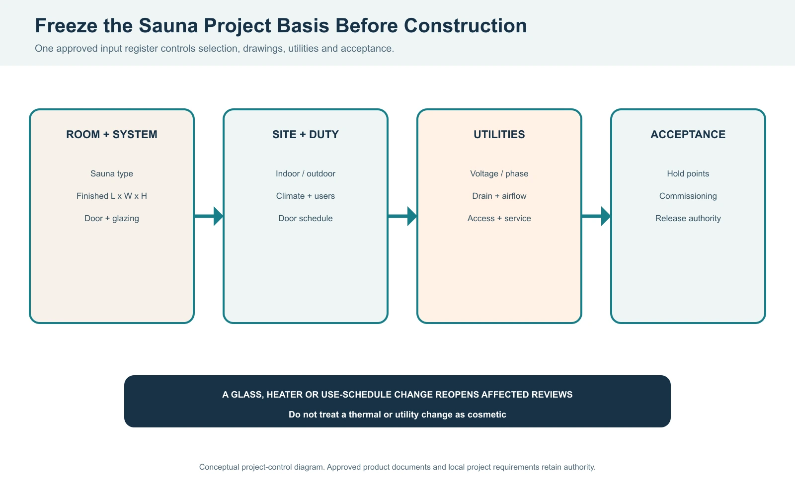
A build becomes unstable when these inputs remain verbal. Use one revision-controlled basis sheet and identify who can approve changes. If a glass wall, door type, heater family or use schedule changes after selection, reopen affected calculations, electrical loads, clearances and drawings instead of treating the revision as cosmetic.
The general guide stops at coordination. A qualified project team must resolve structural capacity, fire separation, accessibility, electrical work, solid-fuel chimney design, waterproofing and permits for the actual jurisdiction. Product instructions define the approved equipment configuration; the article cannot replace them.
Step 2: Calculate Finished Room Volume, Then Record Heater-Load Inputs
Start with finished internal dimensions, not exterior cabin dimensions. For an illustrative rectangular room measuring 2.4 m long, 2.0 m wide and 2.2 m high, geometric volume is 2.4 × 2.0 × 2.2 = 10.56 m³. This number is not a heater recommendation. It is the first input to the selected heater manufacturer’s method.
| Input | Illustrative value | Use | Boundary |
|---|---|---|---|
| Finished internal length | 2.4 m | Geometric volume | Verify after lining build-up |
| Finished internal width | 2.0 m | Geometric volume | Exclude exterior cladding |
| Clear internal height | 2.2 m | Geometric volume | High ceilings affect occupied-zone distribution |
| Geometric volume | 10.56 m³ | Initial selection input | Not final heater size |
| Glass/masonry area | Measured from issued elevations | Approved effective-load adjustment | No universal multiplier is assumed |
| Climate and leakage | Declared design condition | Warm-up and recovery review | Must match final site |
| Door/user schedule | Recorded operating sequence | Commercial recovery review | Unloaded warm-up is insufficient |
Glazing, masonry, uninsulated surfaces, outdoor winter conditions, ventilation and repeated door openings can increase heat demand. Different heater suppliers may use different adjustment methods. Record the exact manual or selection document and its revision. Do not combine a rule from one heater with another product, and do not convert a controller maximum into a promised room temperature.
Step 3: Prepare the Base, Floor, Water Management and Delivery Access
| Interface | Verify before approval | Typical failure | Release evidence |
|---|---|---|---|
| Base/structure | Level, support and design loads | Movement, door misalignment or local damage | Approved structural/base check |
| Floor/water | Cleaning method, falls, waterproof transitions and drain route | Standing water or leakage into adjacent work | Waterproofing and drainage inspection |
| Outdoor weather | Roof drainage, flashing, wind, precipitation and freeze exposure | Water entry or seasonal damage | Issued exterior details |
| Delivery | Opening sizes, turns, lifting path and protection | Cabin cannot reach final location | Measured access plan |
| Service | Heater/control access and removable panels | Installed room cannot be maintained | Service-clearance drawing |
| Utilities | Isolation points and routes | Visible retrofit or unsafe improvisation | MEP coordination record |
A floor drain is not automatically required for every residential cabin, but the project still needs a declared cleaning and water-management method. A commercial room exposed to wet cleaning, frequent water use or public-health procedures normally demands a more formal drainage and waterproofing review. Coordinate the floor-to-wall transition before timber lining hides it.
For outdoor cabins, separate the sauna’s interior vapor control from the exterior weather and drying strategy. Roof pitch, flashings, ground clearance, wind exposure and foundation movement are building-envelope questions. A durable interior lining does not compensate for water entering behind the exterior cladding.
Step 4: Frame the Room, Then Coordinate Insulation, Air and Vapor Control
Frame the room from the issued finished dimensions and provide deliberate backing where benches, heater guards, glazing channels, doors or serviceable equipment will transfer load into the structure. Do not assume interior lining can carry these loads. Before the wall or ceiling is closed, confirm that the framing, openings and backing match the final equipment and interior layout.
| Function | Question to resolve | Inspection point | Do not assume |
|---|---|---|---|
| Structure | What supports lining, benches, heater guards and glazing? | Framing and backing before closure | Lining carries structural loads |
| Thermal control | Is insulation continuous at corners and ceiling? | Gaps, compression and junctions | Nominal insulation alone proves performance |
| Vapor/air control | Where is the continuous control layer? | Seams, edges and transitions | Loose foil pieces form a system |
| Service cavity | How are cables/sensors routed without uncontrolled punctures? | Battens and protected routes | Every penetration can be sealed later |
| Interior lining | Is timber suitable and detailed for movement/drying? | Fasteners, gaps and exposed surfaces | All wood species behave the same |
| Exterior drying | Can the building assembly dry for its climate? | Complete wall/roof design | Interior detail defines exterior vapor behavior |
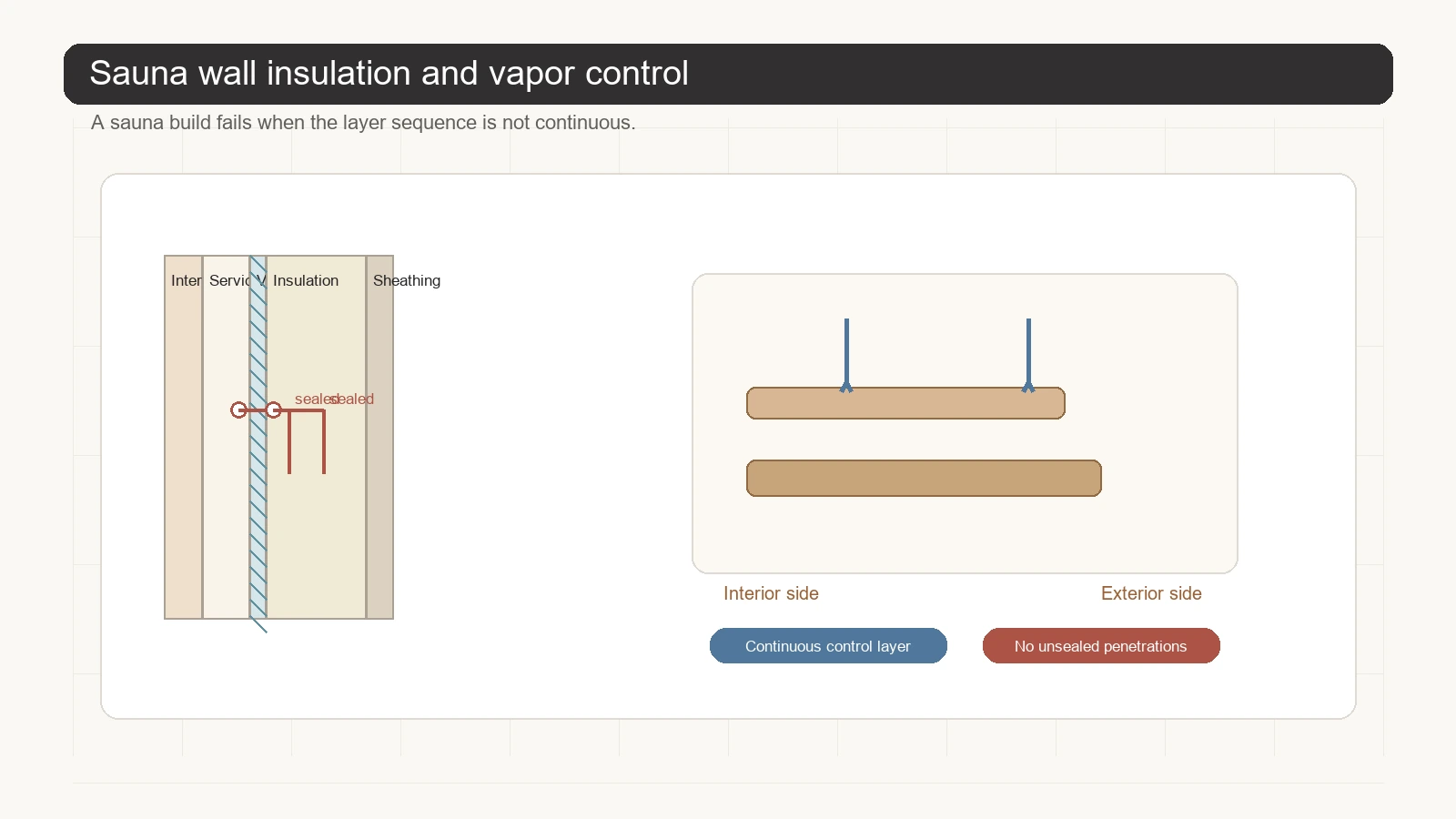
There is no single wall assembly that is correct for every climate and host building. Continuity matters more than a marketing label. Ceiling-to-wall junctions, door frames, glazing channels, cable routes, lights, controls and sensors are common weak points. Maintain a penetration register: identify the opening, location, trade, sealing method, inspection status and photo reference. Unknown openings should block closure.
Materials hidden inside the assembly must be suitable for their expected temperature and moisture exposure. Adhesives, membranes, cable insulation, fixtures and finishes require product-specific confirmation. Avoid unsupported claims that ordinary construction products are automatically safe simply because the exposed face is timber.
Step 5: Rough-In Ventilation and Service Routes Before Timber Lining
Before lining, freeze the intended air-supply and exhaust path together with any fan, heater, controller, sensor, lighting and service routes that must pass through the enclosure. The exact vent position is not universal: it depends on the heater/control system, whether ventilation is mechanical or passive, room geometry and the approved installation method. Coordinate penetrations now so late drilling does not bypass the air/vapor-control layer or place airflow where it interferes with a temperature sensor.
| State | Supply/exhaust condition | Door/heater condition | Evidence |
|---|---|---|---|
| Warm-up | Approved openings and fan state | Door closed; heater sequence recorded | Time trend and occupied-zone map |
| Occupied | Fresh-air path avoids direct short circuit | Representative user and door schedule | Comfort/temperature distribution log |
| Recovery | Same approved path | Door event then closed | Recovery interval and control state |
| Post-use drying | Declared fan/opening routine | Heater/door state per approved procedure | Surface condition and drying check |
| Abnormal | Blocked, reversed or uncertain airflow | Room withheld if safety or drying is unresolved | Correction and qualified release |
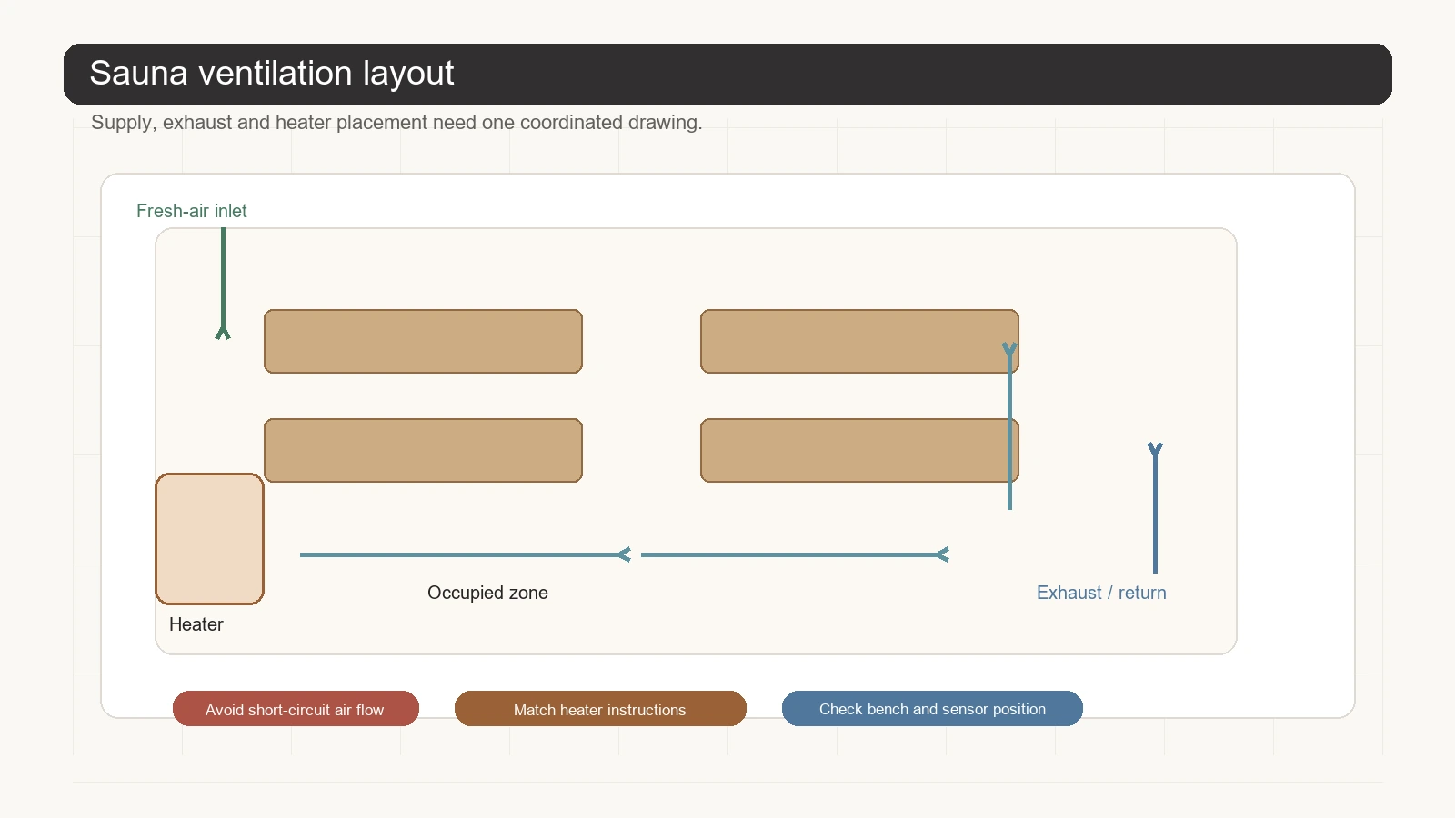
Opening positions differ by heater and ventilation method. Follow the approved equipment and room design instead of copying a generic diagram. A supply placed beside an exhaust may satisfy a nominal opening-area requirement yet short-circuit fresh air without conditioning occupied zones. Conversely, excessive uncontrolled exhaust can increase heat loss and impair recovery.
Drying is an operating requirement. The handover should specify whether fans continue, doors remain open or closed, surfaces are wiped and when the room is released for cleaning. A lower bench that stays damp or a wall cavity showing condensation is not solved by raising the heater setpoint.
Step 6: Lock the Heater, Guard, Sensor, Controller and Utility Supply as One System
Freeze the heater model before finalizing bench edges, guards, wall finishes and service penetrations because the required clearances and sensor position are model-specific. Where rough-in can occur before the final heater is mounted, protect the approved routes and backing so the completed lining does not force an improvised cable path, sensor location or guard geometry later.
| Item | Confirm | Why it matters | Authority |
|---|---|---|---|
| Heater | Selected model and approved room range | Defines installation and operating limits | Manufacturer data |
| Supply | Voltage, frequency, phase, circuit and protection | Mismatch can prevent operation or create hazard | Qualified electrical design/installation as required locally |
| Clearances/guard | Walls, ceiling, benches and user path | Controls fire/contact risk and serviceability | Product instructions + local rules |
| Sensor/high limit | Approved model, location and cable route | Controls cycling and protection | Manufacturer/system instructions |
| Controller | Compatible model, location and environment | Defines operation and diagnostics | Manufacturer data |
| Wood-fired path | Stove, shielding, chimney, combustion air and authority review | Solid-fuel risks differ from electric systems | Qualified fire/chimney design |
Do not move a sensor to make a reading look more favorable or bypass a high-limit device during troubleshooting. Sensor placement is part of the approved control logic. If the displayed value and occupied-zone readings disagree, preserve both, confirm location and instrument method, then diagnose air path, heat loss and configuration.
Fixed wiring, circuit protection, bonding where applicable and solid-fuel chimney work are safety-critical tasks that must follow the selected equipment instructions and the requirements that apply at the installation site. The project must use the requirements applicable to the destination market. Mentioning IEC 60335-2-53 or a local electrical rule describes a reference path; it does not prove that an unspecified HACHILL model is certified.
Step 7: Complete the Interior Fit-Out and Match It to the Construction Route
Once hidden work has been inspected, complete the service battens or cavity required by the chosen assembly, then install the sauna-suitable interior lining, benches, door and glazing. The details must preserve drainage and drying paths, keep serviceable equipment accessible and maintain the heater clearances that will apply to the selected system.
| Element | Verify | Why it matters | Avoid |
|---|---|---|---|
| Interior cladding | Suitable timber/product, fastening method, movement and drying details | Controls finish durability and hot-surface quality | Assuming every wood, coating or adhesive is suitable |
| Benches | Structural backing, stable framing, usable layout and heater relationship | Supports users and defines the occupied heat zone | Fixing benches only to thin lining or blocking service access |
| Door | Operation, hardware, clearance and project egress requirements | Controls access, leakage and safe use | Allowing swelling or misalignment to restrict opening |
| Glazing | Approved glass specification, protected edges and compatible channels/hardware | Changes safety, heat loss and detailing | Changing glass area after heater selection without review |
| Heater zone | Final mounting surface, guard geometry and service access | Preserves model-specific clearances | Trimming the guard or moving the heater to fit finished joinery |
| Decision | Site-built room | Manufactured/prefab cabin | Buyer question |
|---|---|---|---|
| Geometry | High architectural flexibility | Defined module and assembly limits | Is customization worth added coordination? |
| Envelope | Project team owns the full wall, ceiling and floor assembly | Supplier owns more cabin detail; site still owns base, host-building and weather interfaces | Who is responsible for each transition? |
| Services | Trade coordination across project drawings | Defined connection points still require site verification | Are utilities and routes frozen before order? |
| Quality evidence | Hidden-work inspections and trade records | Approved submittal, factory/receiving checks and installation records | What evidence is supplied and what remains site-owned? |
| Schedule risk | More site sequencing dependencies | Delivery, access and connection readiness dominate | What can stop installation? |
| Commercial use | Can be designed around project duty | Offered configuration and commercial duty still require confirmation | Does the selected product match the actual operating schedule? |
Neither route is universally better. A manufactured cabin can reduce the amount of site-built interior work, but it does not eliminate responsibility for the base, host building, utilities, weather exposure, delivery path or local approvals. A site-built sauna can integrate closely with the architecture, but only if structure, envelope, MEP and finish trades work from the same final drawings.
Step 8: Inspect Hidden Work Before It Becomes Inaccessible
| Hold point | Inspect | Record | Release authority |
|---|---|---|---|
| Before framing approval | Geometry, base, openings and backing loads | Dimensions and photos | Designer/project lead |
| Before control-layer closure | Insulation continuity and vapor/air transitions | Marked-up sections and photos | Envelope role |
| Before lining | Penetrations, cable routes, sensor backing and service cavity | Penetration register | MEP + envelope roles |
| Equipment receipt | Model, labels, glass, timber, controls and transit damage | Receiving report | Buyer/site lead |
| Before energization/fire-up | Clearances, guards, wiring/chimney and room condition | Pre-start checklist | Qualified trade |
| Before user release | Controls, ventilation, warm-up, occupied zones and drying | Commissioning record | Operator/project authority |
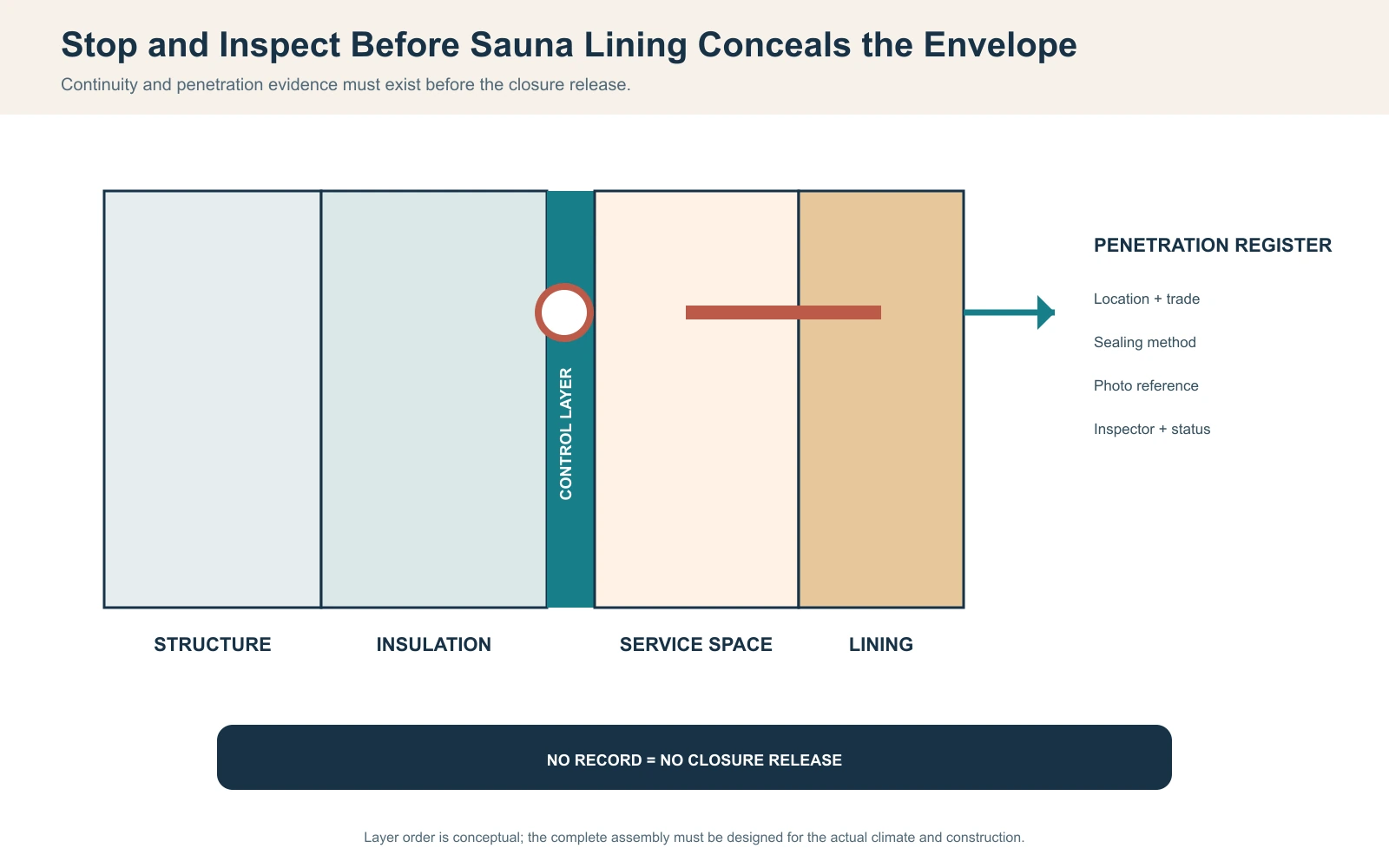
A receiving inspection should compare delivered labels, heater/controller pairing, door handing, glazing protection, timber condition, hardware, documents and accessories against the approved submittal. Record damage before installation. Installing a visibly damaged component can make later transport-versus-installation responsibility difficult to resolve.
Step 9: Commission Construction, Controls, Thermal Duty and Drying Separately
| Stage/time | Measurements or observation | Configuration/event | Disposition |
|---|---|---|---|
| As-built inspection | Dimensions, clearances, guards, door and penetrations | Issued drawing and model IDs | Accept/correct |
| Cold start | Ambient and mapped room/surface points | Door, vents and controls | Protocol confirmed |
| Warm-up intervals | Controller, upper/lower occupied zones and surfaces | Heater state and openings | Continue/hold |
| Occupied recovery | Before/after door and user event | Representative schedule | Duty accepted/restricted |
| Safety/control test | Interlocks, alarms and approved shutdowns | No bypass permitted | Qualified release |
| Post-use drying | Visible moisture and surface condition | Fan/door/cleaning routine | Routine accepted/revised |
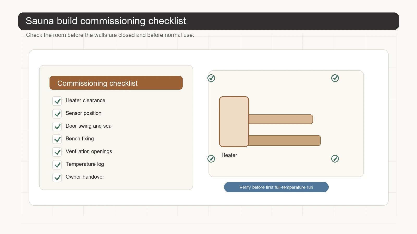
A successful unloaded warm-up does not prove a commercial schedule. Record a representative door-opening and occupancy pattern, then measure recovery using the same locations and instrument method. The room should not be released merely because the controller reaches its setpoint while lower occupied zones remain outside the agreed condition.
Handover evidence should include approved drawings, model and label records, manuals, inspections, as-built penetrations, commissioning logs, cleaning/drying instructions, service access and named open items. Preserve raw readings rather than only a pass certificate.
Trace Common Sauna Build Problems to the Interface That Created Them
Glazing changes after heater selection
Problem: The completed room warms slowly and struggles after door openings.
Possible mechanism to verify: A full glass front may have replaced an insulated wall after the original volume review, changing the effective heat-load basis used for selection.
How to check: Compare issued elevations, measured uninsulated area, heater selection record, supply voltage and warm-up curve.
Prevention/correction: Reopen the approved selection method and utility review; do not promise a result by raising the setpoint.
Ventilation short-circuits at the door
Problem: The control sensor is hot while upper and lower benches feel uneven.
Possible mechanism to verify: Supply and exhaust may be creating a short path that bypasses occupied zones.
How to check: Record vent/fan state and map synchronized readings at the sensor and benches during the same duty.
Prevention/correction: Correct only through the approved heater and room ventilation design, then repeat the same test.
Moisture appears around a cable penetration
Problem: Staining or condensation develops outside the sauna wall after repeated operation.
Possible mechanism to verify: A late cable route may have interrupted the control layer and then been concealed without inspection.
How to check: Review the penetration register, moisture condition and as-built photos; open construction only under an approved repair plan.
Prevention/correction: Dry and repair the assembly, restore continuity and add a pre-close hold point for future penetrations.
These are composite engineering patterns, not claims about a named customer or guaranteed diagnosis. Stop use when there is smoke, scorching, abnormal electrical behavior, damaged glass, unstable structure, unresolved protective-device operation or an unsafe clearance. Qualified personnel must determine release.
For Professional and Commercial Builds, Keep Evidence and Responsibility Clear
| Grade | Evidence | Use | Boundary |
|---|---|---|---|
| A | Applicable authority requirements and approved product instructions | Safety and mandatory constraints | Jurisdiction/model specific |
| B | Issued design, calculations and approved submittals | Construction basis | Must match final revision |
| C | Hold-point inspections and receiving records | Hidden-work and delivery evidence | Only inspected scope |
| D | Traceable commissioning and operating logs | Performance/release decision | Recorded conditions only |
| E | Photo, recollection or marketing statement | Initial observation | Cannot close engineering acceptance |
| Decision | Supplier | Designer/trades | Buyer/operator |
|---|---|---|---|
| Product limits | Provide accurate model data and instructions | Install approved configuration | Operate within limits |
| Room/envelope | Provide interface needs | Design and inspect complete assembly | Freeze use/site inputs |
| Utilities/clearances | State requirements | Verify supply, routes and protection | Prevent unauthorized changes |
| Commissioning | Support product checks | Measure and correct installation | Provide schedule and release authority |
| Records | Provide supplied evidence | Preserve as-built/inspection data | Retain handover and maintenance logs |
| Personal suitability | No clinical authority | No clinical authority | Qualified health/safety policy where required |
Responsibility is interface-specific, not a way to shift every risk to one party. The supplier cannot validate an unseen building envelope; the installer cannot invent heater certification; the operator cannot use a marketing image as commissioning evidence. Name the decision owner and required evidence in the project schedule.
If Acceptance Fails, Correct the Verified Cause and Repeat the Same Duty
| Dispute | Preserve | Immediate control | Closure evidence |
|---|---|---|---|
| Slow warm-up | Ambient, room/glass, heater, supply and time curve | Do not change criteria | Same-start retest after verified correction |
| Uneven benches | Mapped readings, vents, sensor and door events | Restrict use if unresolved | Same-location occupied-duty retest |
| Moisture defect | Photos, moisture condition, penetration and cleaning records | Stop concealment and dry safely | Approved repair inspection plus repeat duty |
| Clearance/guard concern | As-built dimensions and product instructions | Keep affected area closed | Qualified dimensional release |
| Transit vs install damage | Receiving photos, packaging and installation sequence | Quarantine component | Agreed disposition and replacement/repair record |
| Alarm/protection | Original code, configuration and event log | No repeated reset or bypass | Approved technical release |
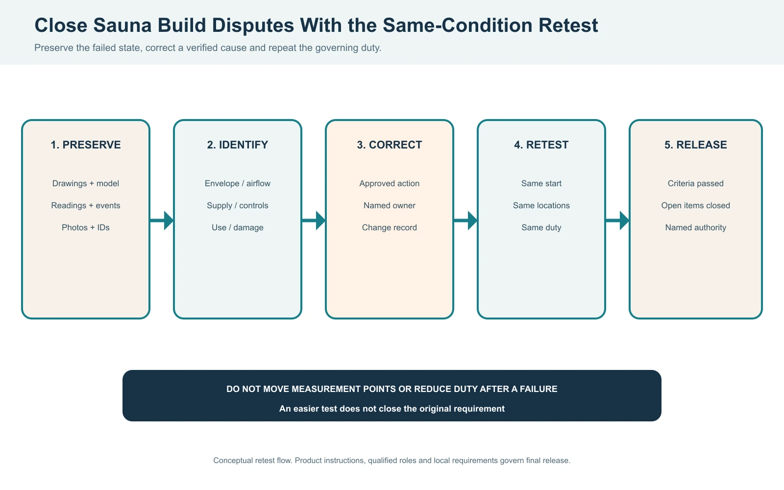
Do not erase an unfavorable curve, move measurement points or reduce the door/user schedule after seeing a failure. If the project intentionally changes the acceptance basis, document who approved the change and why. A favorable easier test does not close the original requirement.
Frequently Asked Questions
Do sauna walls need a vapor barrier?
Most heated sauna room assemblies need a deliberate vapor- and air-control strategy, but the exact layer, position and exterior drying path depend on climate, the host building and the complete wall or roof assembly. Specify the whole system, transitions and penetrations; adding isolated foil without resolving the rest of the assembly is not a complete design.
How do I calculate sauna room size for heater selection?
Measure finished internal length, width and clear height and multiply them for geometric volume. Then use the selected heater manufacturer’s approved method for glazing, masonry and other effective-load inputs. Confirm voltage, clearances, controls, ventilation and operating duty before release.
Does a sauna need ventilation and a floor drain?
A sauna needs an approved ventilation and post-use drying strategy. Drainage depends on water use, cleaning method, floor construction, commercial duty and local requirements. Resolve both before waterproofing and lining conceal the interfaces.
Can I wire a sauna heater myself?
Fixed wiring, circuit protection, sensor and high-limit installation are safety-critical and jurisdiction-specific. Use the selected equipment instructions and qualified electrical personnel as required locally. Do not bypass controls or relocate sensors to change performance readings.
Is a prefab sauna easier than a site-built room?
A prefab cabin can reduce internal construction variability, but the buyer still owns base, access, utilities, weather interfaces and local approvals. A site-built room offers more integration but requires stronger envelope and trade coordination. Compare responsibility and evidence, not only assembly time.
Related HACHILL Resources and Project Inputs
Compare sauna systems
Review the verified sauna category routes before model selection.
Review outdoor sauna systems
Continue the climate, foundation and exterior-interface task.
Review indoor traditional saunas
Compare room and heater-system interfaces for indoor projects.
Define sauna temperature acceptance
Use mapped measurements and declared operating duty during commissioning.
Review product engineering support
Review product-side drawings, fit, interfaces and configuration questions without replacing local architectural, structural or MEP design.
Review sauna heater selection
Continue from room volume and site conditions into electric-versus-wood, controls, sizing inputs and model-specific installation checks.
Review installation support
Use this route when a selected HACHILL product needs manufacturer-side coordination with the actual site, access, base, utilities or installer scope.
Request a sauna project quote
Provide the room, site, utility, duty and documentation inputs already known so product selection and quotation can continue from the correct basis.
RFQ data that prevents avoidable redesign
- Indoor/outdoor site, climate and jurisdiction
- Finished internal dimensions, users, benches, door and glazing
- Sauna type and preferred heater route
- Voltage, frequency, phase and available circuit capacity
- Foundation, floor, drainage and delivery/access plan
- Commercial schedule, cleaning and post-use drying routine
- Required certification scope, drawings, manuals and acceptance evidence
- Quantity, target timeline, branding and packaging scope where applicable
Reference basis
- IEC 60335-2-53:2011+A1:2017+A2:2021 (consolidated) – IEC scope reference for particular safety requirements for sauna heating appliances and infrared cabins; applicability still depends on the product and destination market.
- U.S. EPA moisture-control guidance – general building-moisture principles relevant to keeping assemblies dry.
- NFPA 211 information – reference path for chimney, fireplace, vent and solid-fuel appliance requirements where adopted.
- Harvia ventilation guidance – manufacturer guidance showing that supply/exhaust and temperature-sensor relationships differ by ventilation method and heater configuration; use the selected equipment instructions for the actual project.
- Harvia heater safety-distance guidance – example manufacturer guidance confirming that heater safety distances are product-specific and must be checked against heater documentation rather than copied as a universal value.
Freeze the Sauna Project Basis Before Requesting a Configuration
Send HACHILL the site, finished room dimensions, glazing, users, commercial schedule, heater route, utilities, climate, delivery access and required documentation. HACHILL can review the product route, supplied configuration and manufacturer-side interfaces while local design, permitting and field execution remain with the appropriate project professionals.
Request a Sauna Project Quote