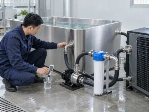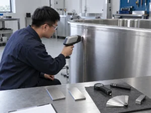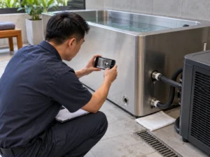
A controlled method for comparing insulated and uninsulated cold plunges across pull-down, holding and recovery duty.
Direct answer: An insulated cold plunge can reduce heat gain through the boundaries that are actually insulated—such as the vessel wall, base, cover or connected pipework—but a fair cooling comparison must change only the declared insulation boundary. Match water mass, initial and target temperature, chiller, circulation, filter state, ambient exposure, cover schedule, sensors and user load. Evaluate pull-down, holding and recovery separately. Otherwise a shorter cooling time may come from a different chiller, flow rate, cover or test condition rather than the insulation. This page explains how to compare and interpret tests; it does not claim a published HACHILL A/B performance result.
This guide is for product buyers, commercial operators, distributors, installers and project engineers who need a repeatable method, not an unsupported savings percentage. It explains how to screen the water-side energy, collect comparable data, inspect thermal bridges and moisture, grade evidence, assign responsibility and close a disputed result.
Page scope: This article owns the insulated-versus-uninsulated comparison method and interpretation, not a universal cooling-performance result. Product pages own exact construction, included accessories and model data. A result applies only to the tested configuration and declared conditions.
Primary effect: Insulation reduces heat flow through the boundary it continuously covers.
Critical control: Keep the cooling system, water mass and exposure equal.
Decision cases: Separate pull-down, holding and recovery.
Evidence needed: Retain raw time series, revisions, events and witness records.
Define Exactly What “Insulated” Means
The word insulated is not a complete specification. Record the material, declared thermal property when verified, installed thickness, coverage, joints, compression, vapor protection and revision. Then identify every break in the layer. A wall panel may be insulated while the rim, frame, base, access door, pipe connections and cover remain exposed. Those paths can dominate a small vessel or a humid site.
Decide whether the comparison is between wall construction, complete vessels, or installed systems. If one sample uses an insulated cover and the other is open, the test measures two systems, not wall insulation alone. This may still be useful, but the report and title of the result must say so.
| Boundary item | Record | Why it matters | Do not assume |
|---|---|---|---|
| Vessel wall and base | Material, coverage, joints, compression | Controls conductive heat gain | Nominal thickness equals installed performance |
| Rim, frame and feet | Continuous or bridged construction | May bypass the insulated field | Small areas are negligible |
| Cover | Construction, fit and open/closed schedule | Controls top-surface load | A cover is automatically included |
| Pipework and fittings | Length, diameter, exposure and insulation | Adds external heat gain and condensation paths | Tub insulation covers the loop |
| Equipment enclosure | Air path and service openings | Affects heat rejection and moisture | More insulation is always helpful |
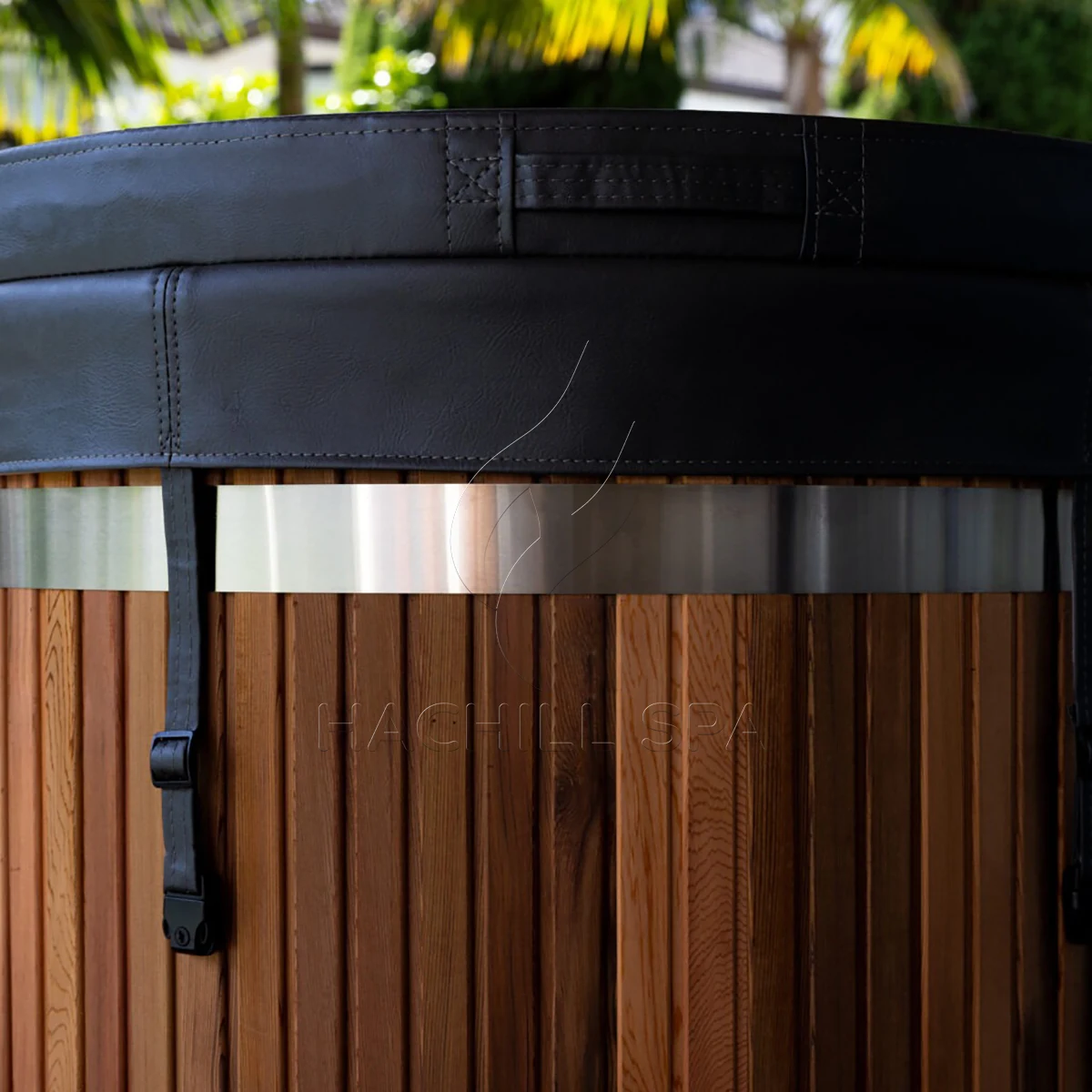
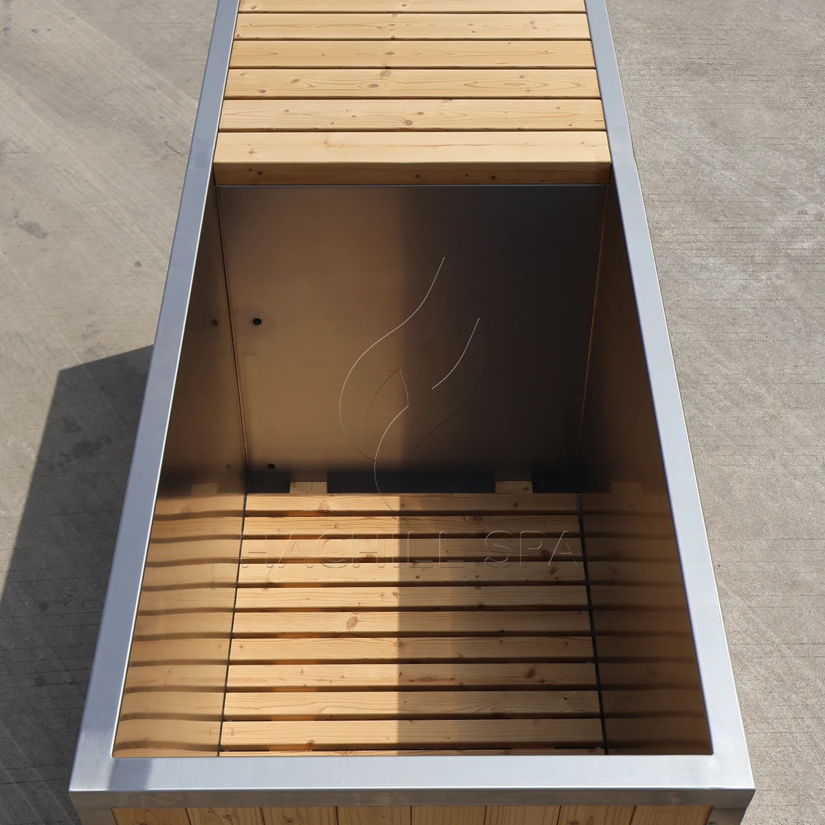
Do not infer hidden construction from a product photograph. For procurement, request an approved section drawing or model-specific construction schedule. If the supplier cannot verify a field, mark it open. An open field is safer than converting a category label into a contractual property.
Separate Pull-Down, Holding and Recovery
Insulation does not influence every operating state in the same way. During pull-down, stored heat in the water can dominate and a high-capacity chiller may hide a smaller difference in ongoing heat gain. During closed-cover holding, environmental heat gain and control behavior become more visible. Recovery adds people, refill water, open-cover time and operational events.
| Duty case | Start rule | Primary observation | Invalid conclusion |
|---|---|---|---|
| Pull-down | Declared initial water and target | Temperature-time trend | One endpoint proves insulation savings |
| Holding | Stable target and declared cover state | Heat gain, cycling or input over time | Overnight result predicts occupied operation |
| Recovery | Timestamped user or refill event | Return trend and control response | Pull-down test proves recovery |
| Abnormal | Flow, airflow, leak or protection event | Protection and stop response | Bypass protection to finish a run |
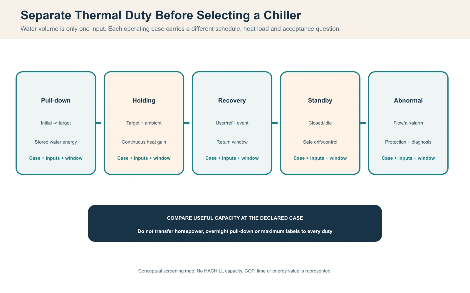
Declare the observation window and start/stop rule before data are reviewed. A system that runs continuously during an intentional hot pull-down is not automatically undersized. A system that cycles during low-load holding is not automatically oversized. The duty case and load history give run time its meaning.
Use the Water-Side Energy Calculation as a Screen
The stored-water energy screen is Q = m × cp × ΔT, where Q is thermal energy, m is water mass, cp is the specific heat of water and ΔT is the required temperature change. Keep units consistent. This calculation is useful because it forces the buyer to define operating water mass and temperature change before comparing cooling claims.
| Input | Example planning value | Use | Boundary |
|---|---|---|---|
| Water mass, m | 500 kg | Stored-water energy | Verify operating mass or derive it from measured volume using a declared density basis. |
| Specific heat, cp | 4.18 kJ/kg-K | Water property in screen | Representative screening value near room temperature; use condition-specific property data for formal work. |
| Temperature change, ΔT | 20°C to 10°C = 10 K | Required water temperature change | Does not include vessel or ongoing heat gain |
| Q = m × cp × ΔT | 20,900 kJ, about 5.8 kWh thermal | Compares stored-water duty | Not electrical consumption or elapsed time |
For the labeled example, 500 kg × 4.18 kJ/kg-K × 10 K gives 20,900 kJ, or about 5.8 kWh of thermal energy. The 4.18 kJ/kg-K value is a rounded screening property for liquid water near room temperature; a formal calculation should use an appropriate property basis for the actual temperature and fluid composition. This is not a HACHILL product rating, measured site result or electrical-energy promise. It excludes vessel thermal mass, heat entering during the run, pump heat, control behavior, defrost or protection events and differences between rated and field cooling capacity.
A preliminary time screen may compare total thermal duty with cooling capacity at a declared condition, but horsepower and electrical input are not cooling capacity. Even a capacity-based division is only a planning estimate until the actual condition, flow and complete-system performance are verified.
Write a Matched-Test Protocol Before Starting
A defensible paired test changes the intended insulation variable and holds the remaining inputs equal. Use the same vessel geometry where possible. If two physical vessels are required, record surface area, water mass, materials, connected pipe volume and all construction differences. Randomize run order or alternate configurations when practical so a changing room or weather condition does not consistently favor one sample.
| Variable | How to control | Evidence | Hold test if |
|---|---|---|---|
| Water | Same measured operating mass and chemistry | Fill record and level reference | Volume basis differs |
| Cooling loop | Same chiller, piping, pump and clean filter | Configuration photo and flow record | Flow or filter state is unknown |
| Initial and target state | Same mixing and start tolerance | Time-series readings | One sample starts colder |
| Environment | Comparable intake air, humidity, wind and solar load | Local sensor log | Weather app replaces site reading |
| Cover and user load | Same timestamped schedule | Event log | Open periods differ |
| Instrumentation | Same sensors, locations and interval | Instrument register | Sensor placement changes |
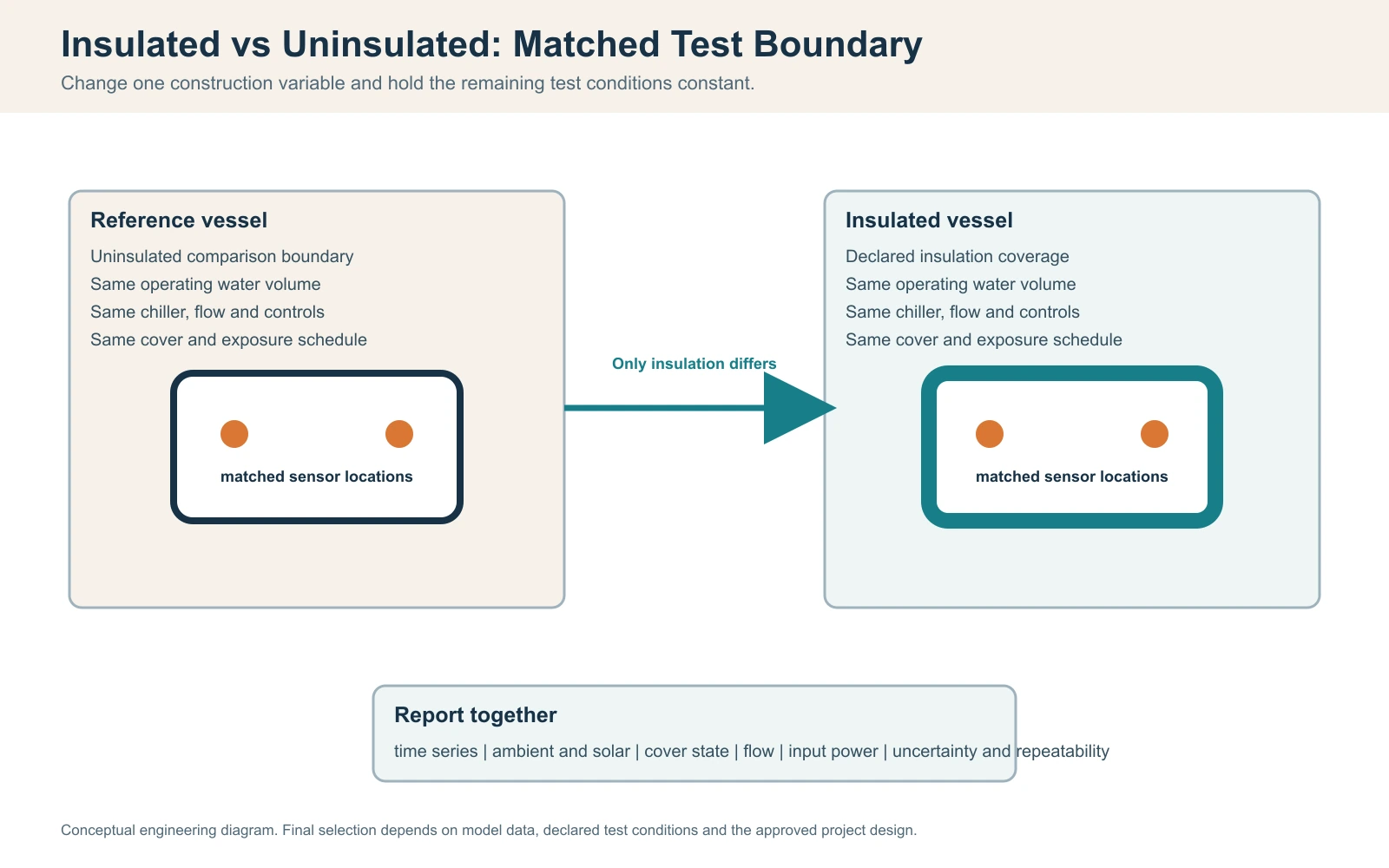
Define stabilization, mixing and endpoint rules. For example, the run should not begin merely because one sensor briefly crosses a number. State how water is mixed, where temperature is measured, what tolerance starts the clock, what target ends the run and how an interruption is treated. The protocol should also say whether the cover remains closed, when the circulation pump starts, and whether the complete system or only a component is being metered.
Repeat runs are most important when the claimed improvement is small. Preserve every valid trace. Removing an inconvenient run without a documented exclusion rule turns an engineering comparison into selective reporting.
Collect Synchronized Data That Can Explain the Difference
A controller screenshot records a moment; it does not establish what happened throughout a test. Use a shared time base and fixed interval for water temperature, local air and humidity, cooling call, compressor or chiller run state, alarms, flow evidence, filter state and cover/user events. Record sensor identity, location, units and available verification or calibration information.
| Field | Method | Decision use | Evidence issue |
|---|---|---|---|
| Water temperature | Fixed points with declared mixing rule | Trend and endpoint | Sensor near inlet biases result |
| Ambient and humidity | At product and condenser intake | Normalize heat and dew-point conditions | Remote weather record only |
| Flow/filter state | Approved measurement or declared proxy | Verify heat-transfer condition | No record after filter service |
| Cooling/control state | Timestamp call, run, cycle and alarms | Explain duty behavior | Reset erases history |
| Cover/user/refill events | Timestamp each event | Separate imposed load | Staff recollection only |
| Electrical input | Defined meter boundary by qualified role | Compare same system scope | Compressor-only vs whole-system |
| Risk | Observed sign | Check | Treatment |
|---|---|---|---|
| Sensor offset | Parallel sensors disagree | Co-locate before/after run | Correct or include uncertainty |
| Poor mixing | Different depths show gradients | Use declared mixing and locations | Do not choose favorable point |
| Ambient drift | Runs occur in different weather | Compare synchronized local logs | Repeat or limit conclusion |
| Control hysteresis | Different start/stop thresholds | Record setpoint and actual calls | Normalize before comparison |
| Run-to-run variation | Effect is smaller than spread | Repeat both configurations | Report inconclusive |
Place the ambient sensor where it represents the product and condenser intake rather than a distant wall or weather service. A discharge-air sensor should not be mistaken for room temperature. Water sensors near the cold inlet can report a colder condition than the bulk water if mixing is poor. Record at least the location and mixing rule so another reviewer can interpret the trace.
If energy input is compared, freeze the meter boundary. A whole-system meter that includes pump and controls is not directly comparable with a compressor-only reading. Use qualified personnel for regulated electrical measurement, and never open energized equipment merely to complete a blog-style test.
Inspect Thermal Bridges, Condensation and Serviceability
When a cold surface falls below the local dew point, moisture can condense. Continuous insulation and vapor control may raise the outer surface temperature, but gaps can move condensation to the rim, fittings, frame or service openings. The absence of visible moisture on one panel does not prove the complete enclosure is dry.
| Location | Possible mechanism | Inspection | Corrective path |
|---|---|---|---|
| Rim and frame | Insulation discontinuity | Surface temperature and condensation map | Review continuity and approved detail |
| Pipe penetrations | Cold fitting meets warm humid air | Dry inspection before and after run | Seal/insulate using approved method |
| Base and feet | Structural bridge or trapped water | Access and drainage check | Restore drainage and inspect materials |
| Service enclosure | vapor entry or leak | Trace moisture source | Do not conceal until cause is closed |
| Insulation itself | Wet, compressed or displaced material | Revision-linked construction record | Replace/repair per approved specification |

Inspect before, during and after each run. Distinguish condensation from a water leak by drying the area, observing timing and tracing the source under an approved procedure. Wet insulation can lose performance, retain contaminants or conceal corrosion. Do not seal the space until the source, affected material and drainage path have been reviewed.
Added insulation must not block condenser airflow, pump ventilation, drains, service panels or required clearances. A thermal improvement that makes inspection or repair impractical may create a larger project risk. Include service access and replacement method in the comparison decision.
Interpret the Complete Trace, Not One Endpoint
Compare the temperature-time curves, not only the time at which one displayed sensor reaches target. Review the initial slope, behavior near target, control calls, ambient drift and any alarm or event. Pull-down can look similar while holding behavior differs, or a shorter result can disappear when start temperature and flow are normalized.
| Observation | Possible explanation | Next check | Do not claim |
|---|---|---|---|
| Faster pull-down | Lower heat gain or another changed input | Matched boundary and full trend | Universal time saving |
| Similar pull-down | Cooling output dominates stored-water duty | Holding test and uncertainty | Insulation has no value |
| Longer off-cycle | Lower holding load or different controls | Control band and sensor state | Guaranteed energy percentage |
| Condensation moves to rim | Thermal bridge remains | Surface/moisture map | No condensation risk |
| Higher input in one run | Ambient, flow, cover or meter scope differs | Normalize all inputs | Insulation caused the difference |
Report the result in a condition-linked sentence: what configuration was tested, under which ambient and cover schedule, with which water mass and cooling loop, for which duty case. Avoid turning a development observation into a universal percentage. A test in a mild indoor room does not prove the same difference in direct sun, humid air or a busy commercial schedule.
Common Engineering Scenarios That Produce a False Conclusion
Scenario 1: the cover, not the wall, creates the result
Problem: The insulated sample reaches target sooner, but its cover stayed closed while the reference was opened for checks.
Cause: Surface heat gain and evaporation changed with the wall construction.
Check: Compare the event log, cover timestamps and complete traces.
Prevention: Use identical cover practice or label the output as a complete-system comparison.
Scenario 2: no pull-down difference is treated as proof that insulation has no value
Problem: Both samples show similar pull-down time.
Cause: Stored-water duty and cooling capacity dominate the short test while heat-gain differences are within measurement variation.
Check: Review repeatability, then run a declared holding test.
Prevention: Separate duty cases and define a minimum detectable difference before making a claim.
Scenario 3: condensation appears after an insulation retrofit
Problem: Side panels remain dry, but moisture collects at fittings and the base.
Cause: Discontinuous vapor control or a thermal bridge concentrates condensation at the remaining cold path.
Check: Map surface/moisture conditions and rule out leakage.
Prevention: Review continuity, drainage and service openings as one assembly before closing the enclosure.
Separate Test Evidence From Project Responsibility
Product comparisons become difficult when parties use the same word for different proof. A model photo may confirm appearance but not hidden insulation. A calculation may screen heat duty but not field performance. A controlled final-system test can support acceptance only for the declared condition. Use an evidence grade in the decision register so a planning assumption is not mistaken for release evidence.
| Grade | Evidence | Permitted use | Boundary |
|---|---|---|---|
| A | Witnessed paired test on final declared configuration | Condition-specific acceptance | Tested conditions only |
| B | Exact-model controlled test with full method | Offer comparison and planning | Reconcile site differences |
| C | Revision-linked drawing, calculation or component record | Design screening and interface review | No final field proof |
| D | Qualified estimate with assumptions | Budget and open-item planning | Must be verified |
| E | Photo, label or marketing summary | Orientation only | Cannot support performance acceptance |
| Decision | Supplier | Buyer or project team | Qualified local role |
|---|---|---|---|
| Configuration | Issue revision-linked construction scope | Freeze required comparison | Review site interfaces |
| Test method | State product limits and available evidence | Approve variables and witnesses | Verify regulated measurement/work |
| Site conditions | State airflow, hydraulic and access needs | Provide accurate environment and schedule | Install and commission |
| Acceptance | Provide records and correction evidence | Preserve baseline and sign disposition | Authorize safety release where required |
| Change control | Notify substitutions/revisions | Assess affected criteria | Retest affected interface |
The supplier should identify configuration and available evidence; the buyer or project team should freeze the required use cases, site conditions and witnesses; qualified local professionals should perform regulated installation and measurements. Compatibility language does not transfer responsibility for structure, drainage, electrical protection, ventilation or public-use approval.
Decide How a Disputed Result Will Be Retested
Acceptance criteria should name the configuration revision, duty case, starting condition, target, observation window, allowed deviations, instruments, witnesses and required records. Avoid a criterion such as “insulated tub cools faster” without a minimum valid difference and a method for uncertainty. When the difference is within normal run-to-run spread, report it as inconclusive.
| Issue | Preserve | Correction | Retest or release rule |
|---|---|---|---|
| Unmatched conditions | Both raw logs and configuration photos | Re-establish matched boundary | Repeat both cases |
| Sensor or meter dispute | Instrument IDs and original data | Verify or replace instrument | Repeat affected measurements |
| Flow or airflow deviation | Alarms, filter, pipe and intake records | Restore approved condition | Repeat thermal case |
| Moisture or leak | Photos, timestamps and material state | Identify source and approved repair | Leak/moisture check before thermal run |
| Construction revision | Old and new drawings plus change notice | Assess affected boundary | Prior result applies only if equivalence is justified |
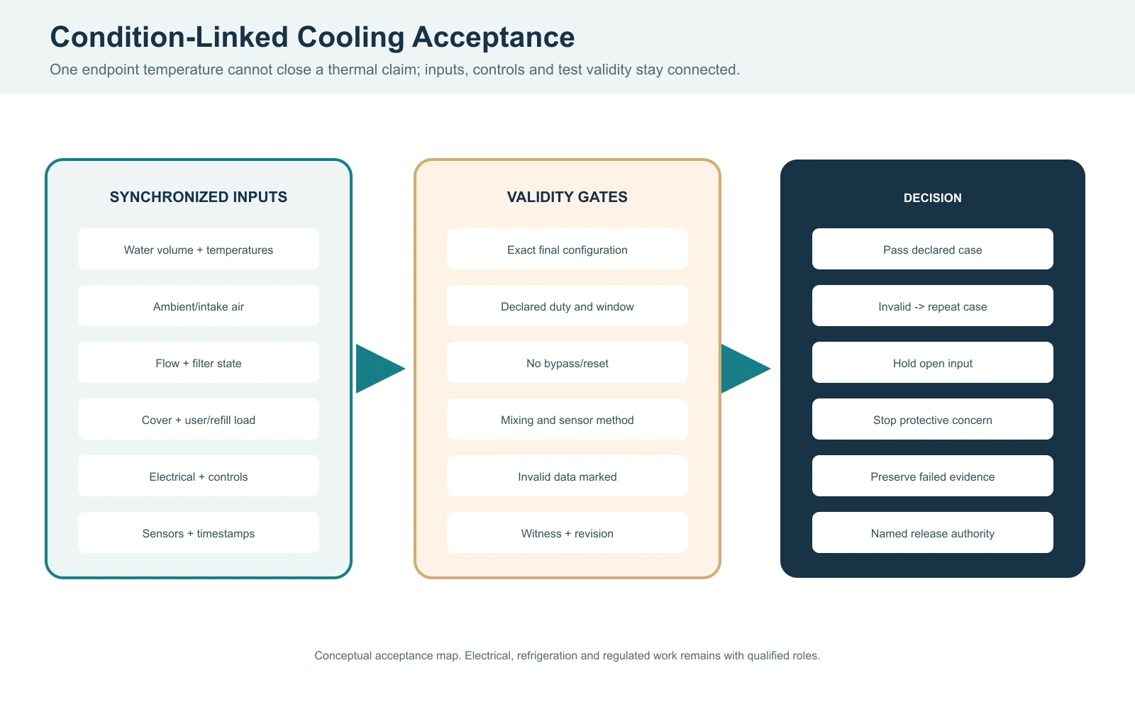
Preserve the failed or disputed record. Correct one verified cause at a time and retest the affected case under the same boundary. A corrected test proves the corrected condition; it does not erase the original deviation. If construction changes after the test, issue a change record and decide whether equivalence can be justified or the comparison must be repeated.
Stop condition: Stop for leakage, wet electrical equipment, loss of flow, repeated protection trips, uncontrolled condensation entering materials or service spaces, unsafe water condition, or any product/manual limit. Refrigerant, fixed electrical and other regulated work requires qualified personnel.
Carry the Comparison Into Receiving and the RFQ
At receiving, compare model/serial identity, crate condition, visible damage, included parts, loose fittings and document revisions with the approved order. Photograph exceptions before installation. Inspect insulation or cover details only where access is permitted; do not dismantle an enclosure in a way that affects safety or warranty merely to verify a marketing claim.
Commission under the approved procedure: level support, leak tightness, valve state, priming, flow, filter, controls, temperature indication, treatment, drainage and alarms. Record local ambient and water conditions for any performance observation. Keep site acceptance separate from a supplier development test.
Information to Include in an Insulation-Comparison RFQ
- Application and commercial or residential duty
- Operating water volume and geometry
- Initial and target water conditions
- Indoor/outdoor climate and solar exposure
- Insulation boundary and construction evidence
- Cover construction and use schedule
- Chiller, circulation, filter and pipe arrangement
- Pull-down, holding and recovery objectives
- Condensation, drainage and service-access plan
- Voltage, frequency, phase and destination
- Test method, witnesses and acceptance records
- Quantity, branding and documentation scope
HACHILL can review the product-family and project inputs without converting open fields into promises. Exact construction, performance, certification and included scope must remain tied to the selected model, destination and approved documents.
Frequently Asked Questions
Does insulation make a cold plunge cool faster?
It can reduce heat entering through the surfaces it covers, but pull-down also depends on water mass, starting and target temperature, actual cooling capacity, flow, ambient exposure and cover practice. A valid comparison controls those variables and reports the complete temperature-time trace. A faster result from two different products cannot be attributed to insulation alone.
What is the best way to compare insulated and uninsulated cold plunges?
Use a paired protocol with the same operating water mass, chiller, circulation loop, clean filter, sensor positions, initial and target conditions, local ambient exposure and cover schedule. Record water, air, humidity, control state, flow evidence and events at synchronized intervals. Repeat both configurations when the observed difference is close to normal test variation.
Can I calculate cold plunge cooling time from water volume?
Water volume supports an energy screen using Q = m × cp × ΔT, but it does not establish field time. The vessel, ongoing heat gain, cooling-capacity test condition, flow, controls and losses also matter. Divide by capacity only as an explicitly bounded planning estimate, not as a guaranteed pull-down result.
Does thicker insulation always perform better?
Not automatically. Thermal properties, continuity, compression, joints, moisture protection and thermal bridges determine the installed boundary. Added material can also affect service access, drainage or equipment airflow. Compare approved construction details and test evidence rather than thickness alone, and keep exact model claims tied to the applicable revision.
When should an insulation comparison test be stopped?
Stop for leakage, wet electrical equipment, loss of circulation, repeated protection trips, unsafe condensation, uncontrolled water condition or any instruction/manual limit. Preserve the original readings and alarms before correction. A qualified person should clear regulated electrical, refrigeration or safety work, and the affected case should be retested after the cause is documented.
Reference Basis
- NIST SI Units – Temperature — temperature units and interval conventions for test records.
- NIST Chemistry WebBook – Water — liquid-water heat-capacity data supporting the rounded screening property used in the energy example.
- U.S. EPA Moisture Control Guidance — dew-point and condensation principles for cold surfaces and moisture-control review.
- CDC Model Aquatic Health Code — public-aquatic-facility guidance; it is not federal law and applicability depends on local adoption.
- NSF/ANSI/CAN 50 Cold-Plunge Requirements Overview — scope context for cold tubs with circulation, treatment or disinfection systems; this is not a HACHILL certification claim.
Technical boundary: Approved product documents, local building, electrical and public-health requirements, qualified trades and the authority having jurisdiction take priority over this general guide. Standards and guidance apply only within their stated scope and adopted jurisdiction. No exact HACHILL cooling time, energy saving, insulation property, certification or medical result is claimed here.
Turn the Comparison Into a Project Brief
Send the water volume, initial and target condition, ambient exposure, cover schedule, cooling loop, duty cases, destination, quantity and required test evidence. HACHILL can review a model or product-family route while keeping unverified fields open.